Table of Contents
Advertisement
Quick Links
Advertisement
Table of Contents

Related Manuals for Itowa IT3R22


Summary of Contents for Itowa IT3R22
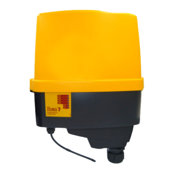
- Page 1 User's manual Receiver IT3R22 ...
- Page 2 ANY REPRODUCTION OF ALL OR PART OF THIS MANUAL IS STRICTLY FORBIDDEN WITHOUT PRIOR WRITTEN PERMISSION FROM ITOWA. OTHERWISE, ITOWA RESERVES THE RIGHT TO TAKE SUCH ACTION AS IT DEEMS APPROPRIATE UNDER CURRENT LEGISLATION. ITOWA RESERVES THE RIGHT TO MODIFY THIS MANUAL WITHOUT PRIOR NOTICE.
-
Page 3: Table Of Contents
Receiver IT3R22 USER'S MANUAL INDEX: 1. INTRODUCTION 1.1. GCFI VERSION 2. GENERAL TERMS AND CONDITIONS FOR THE CORRECT USE OF THE RECEIVER 3. DESCRIPTION OF THE RECEIVER 3.1. GENERAL DESCRIPTION 3.1.1. STANDARD RECEIVER 4. TECHNICAL FEATURES 4.1. GENERAL CHARACTERISTICS 5. -
Page 4: Introduction
Receiver IT3R22 USER'S MANUAL 1. INTRODUCTION The manual you have in your hands is a guide to the correct use of the ITOWA IT3R22 multi-frequency receiver. This receiver, together with the associated remote control, is specially designed to be controlled remotely, without cables, and to act directly on electromechanically driven machinery. -
Page 5: Description Of The Receiver
In the event of a malfunction of the equipment, specific control circuits are in charge of deactivating the receiver's working manoeuvres. For extra safety all monitoring circuits are duplicated. Fig. 3-3. Receiver IT3R22... -
Page 6: Standard Receiver
Receiver IT3R22 USER'S MANUAL 3.1.1. STANDARD RECEIVER In case you need to remove the controller card follow these instructions: Lift the tab (1). Remove the controller. Fig. 3-4. Details of the tab Receiver Controller Fig. 3-5. Details of the receiver... -
Page 7: Technical Features
Receiver IT3R22 USER'S MANUAL 4. TECHNICAL FEATURES 4.1. GENERAL CHARACTERISTICS System: MULTI-FREQUENCY Frequency: ISM-BAND Order response time: <50 ms Active emergency time: <50 ms Passive emergency time: 1600 ms Range of action: 100 meters Temperature range: From -20 to 70 ºC Frequency bands: 434.050 to 434.775 MHz... - Page 8 Receiver IT3R22 USER'S MANUAL Fuses: Emergency stop manoeuvre : 8 A Connection: Via 48-pin Itowa connector Dimensions: External 374 x 274 x 126 mm Fixation: Bichromated steel 3 mm Mounting: By bolts or magnetic (optional) Weight: With fixation 4,20 kg...
-
Page 9: Installation And Start-Up
Whenever the installation allows it, the antenna should be free of metal shields to achieve a better radio link and avoid communication cuts. Itowa is not responsible for improper installation. 5.1.1. STANDARD FIXING OF THE RECEIVER Fig. 5-1. Standard fixation... -
Page 10: Magnetic Fixing Of The Receiver (Optional)
Receiver IT3R22 USER'S MANUAL Mount the fixation on a stable, robust support of proportionate measures to this fixation. Place the fixation in vertical position using if necessary the alternative holes to the two central ones shown in figure 5-2. -
Page 11: Dismounting With Magnetic Support
Receiver IT3R22 USER'S MANUAL 5.1.3. DISMOUNTING WITH MAGNETIC SUPPORT Fig. 5-3. Steps for dismantling the receiver with magnetic holder Due to the magnetic force of the magnets, the following instructions should be followed when uninstalling the device: Loosen the DIN 6921 M6 screws (1) with a No. 10 open-end spanner. - Page 12 Receiver IT3R22 USER'S MANUAL For further details on the connection, please refer to the relay output sheet provided with the receiver. The standard receiver internally allows the selection of three different voltages (230 Vac, 115 Vac, or 48 Vac). For other models, we have receivers that are supplied with a single voltage of 24 Vac/dc or 12 Vac/dc.
- Page 13 ATTENTION!: IF THE STOP MANOEUVRE DOES NOT REQUIRE INDEPENDENT CONTACTS, A JUMPER MUST BE MADE BETWEEN TERMINALS 43 AND 45, AND THE MANOEUVRE MUST BE CONNECTED TO TERMINALS 41 AND 47. Itowa is not responsible for improper installation. Selectable supply voltage on the receiver board...
- Page 14 Receiver IT3R22 USER'S MANUAL In models with optional relay and/or analogue output controls, the device internally incorporates one of the following expansion modules. The connection of the controls associated to each one of them is indicated in the specific documentation delivered with the device.
-
Page 15: Start-Up
Receiver IT3R22 USER'S MANUAL 5.3. START-UP Once the receiver has been installed and connected, the LEDs on the front of the machine will light up sequentially when the main switch is activated. The functionality of each LED varies depending on the state of the receiver, but in this case they only indicate a check of the receiver. -
Page 16: Receiver Maintenance
This check should be carried out by a Technical Assistance Service accredited by ITOWA, as poor waterproofing can cause irreparable damage to the equipment. ATTENTION!: BEFORE ANY MANIPULATION, PROCEED TO DEACTIVATE THE MAIN SWITCH OF THE MACHINE. -
Page 17: Working Channel Display
Receiver IT3R22 USER'S MANUAL 7. WORKING CHANNEL DISPLAY 7.1. DISPLAY OF THE EQUIPMENT CODE If you wish to know the device code, the receiver allows you to display it through a simple sequence of pulses. Fig 7-1. Location of the button on the base plate of the receiver. -
Page 18: Display Of The Working Channel
Receiver IT3R22 USER'S MANUAL The example code is 01A38E: Code Number of pulses in LED The sequence in the example above would be (P1 is the button): All LEDs are blinking. Blinking of all LEDs except S1 until P1 is pressed. -
Page 19: Scanning
Receiver IT3R22 USER'S MANUAL 8. SCANNING The receiver has some systems for detecting anomalies in the event that other equipment or systems interfere with the communication between the transmitter and the receiver. These systems include frequency scanning, which will be used to scan the entire band and find the frequency channels that are or have been occupied by some other device emitting within the same band. -
Page 20: Change Of Working Frequency (Not Valid For Gcfi Versions)
Receiver IT3R22 USER'S MANUAL Start with the lowest free channel. 11 units will be added for the next channel to be displayed, as long as the band in which you are working allows it. If the result is higher than the maximum number of band channels, the maximum number of band channels will be deducted. -
Page 21: Led Information
Receiver IT3R22 USER'S MANUAL 10. LED INFORMATION ICON INDICATION LED off. Slow blinking. LED off with rapid blinking on. LED on with rapid blinking off. LED on steady. STATUS LED S1 Receiver running. Slight loss of radio frequency signal. - Page 22 Receiver IT3R22 USER'S MANUAL STATUS Receiver at rest. Received radio frequency signal recognized as its own. Received radio frequency signal NOT recognised as its own. Error in radio frequency reception (if transmitter is running). STATUS LED PWR Correct supply.
-
Page 23: Possible Incidents And Solutions
Receiver IT3R22 USER'S MANUAL 11. POSSIBLE INCIDENTS AND SOLUTIONS INCIDENT STATUS SOLUTION Check key status or selector switch in ON position. None of the transmitter indicators (TX) and Check that the battery is correctly inserted. (BAT) are illuminated. Check the charge status of the battery or replace it directly with a charged one. - Page 24 Receiver IT3R22 USER'S MANUAL INCIDENT STATUS SOLUTION Transmitter and The receiver is connected Place the cable button panel/cab instead of the receiver start but to the machine but the remote control and if it does not work either, the the machine does machine is still not working.
-
Page 25: Recycling
Receiver IT3R22 USER'S MANUAL 12. RECYCLING INFORMATION PROPER MANAGEMENT ELECTRICAL ELECTRONIC EQUIPMENT WASTE (RAEE) At the end of the device's life, it shouldn't be disposed of mixed with general waste. It can be delivered, free of charge, to specific collection centres, differentiated by the local authorities, or to distributors who provide this service. - Page 26 Receiver IT3R22 USER'S MANUAL www.itowa.com SINDITO, S.L. Faraday, 159 08224 Terrassa (Barcelona) España Tel. +34 93 733 98 50...
Need help?
Do you have a question about the IT3R22 and is the answer not in the manual?
Questions and answers