Table of Contents
Advertisement
Quick Links
Advertisement
Table of Contents

Related Manuals for Itowa MF2


Summary of Contents for Itowa MF2
- Page 1 User manual Receiver MF2 ...
- Page 2 IT’S FORBIDDEN TO FULLY OR PARTIALLY REPRODUCE THIS MANUAL WITHOUT THE PRIOR WRITTEN AUTHORISATION FROM ITOWA. IN THE EVENT OF INFRINGEMENT, ITOWA RESERVES THE RIGHT TO TAKE THE ACTION IT DEEMS NECESSARY IN ACCORDANCE WITH THE CURRENT LAW. ITOWA RESERVES THE RIGHT TO MODIFY THIS MANUAL WITHOUT PRIOR...
- Page 3 Receiver MF2 USER MANUAL INDEX: 1. INTRODUCTION 1.1. VERSIÓN GCFI 2. GENERAL RULES FOR THE CORRECT AND SAFE USE OF THE RECEIVER 3. DESCRIPTION OF THE RECEIVER 3.1. GENERAL DESCRIPTION 3.1.1. RECEIVER 16 RELAYS 3.1.2. RECEIVER 24 AND 32 RELAYS 4.
- Page 4 USER MANUAL 1. INTRODUCTION The manual you are holding in your hands is a guide to the correct use of the ITOWA MF2 multi- frequency receiver. This receiver is specially designed to be remotely controlled, without cables, and to act directly on electromechanically driven machinery.
-
Page 5: Description Of The Receiver
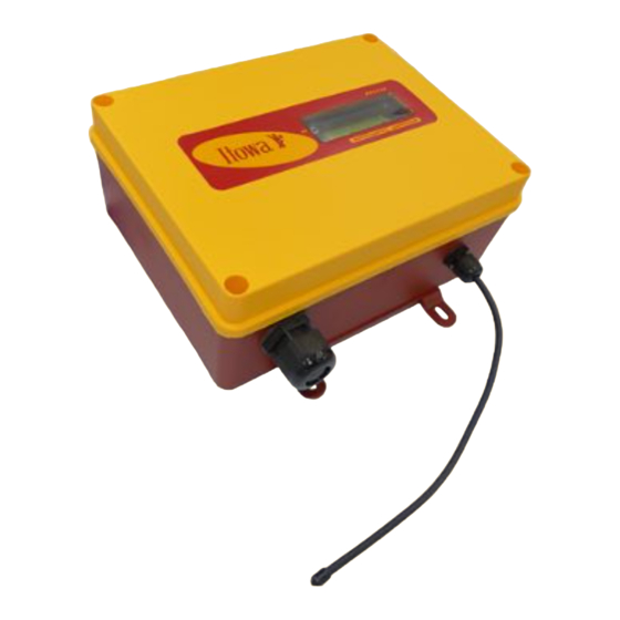
Receiver MF2 USER MANUAL 3. DESCRIPTION OF THE RECEIVER 3.1. GENERAL DESCRIPTION The receiver assembly consists of a watertight plastic casing (IP65) inside which the different electronic systems for the reception of commands and the activation/deactivation of the appropriate relays for each manoeuvre of the machine are located. - Page 6 Receiver MF2 USER MANUAL 3.1.2. RECEIVER 24 AND 32 RELAYS Fig. 3-4. receiver 24 and 32 relays...
-
Page 7: Technical Specifications
Receiver MF2 USER MANUAL 4. TECHNICAL SPECIFICATIONS 4.1. GENERAL FEATURES System: MULTI-FREQUENCY Frequency: ISM-BAND Order response time: <50 ms Active emergency time: <50 ms Passive emergency time: 1600 ms Range of action: 100 meters Temperature range: From -20 to 70 ºC Frequency bands: 433.050 to 434.775 MHz... - Page 8 Receiver MF2 USER MANUAL Fuses: Emergency Stop maneuver: 8 A Primary transformer: 1 A / 230V ; 2 A / 115V ; 4 A / 48V Secondary transformer: 4 A Connection: Using a connector to power strips Dimensions: Exterior (16 relays):...
-
Page 9: Installation And Start-Up
Whenever the installation permits it, the antenna should be free of metallic shielding to achieve a better radio link and to avoid communication cuts. Itowa is not responsible for improper installation. 5.2. CONNECTION It is recommended to connect the equipment with a standardised multi-cable hose as the one used to connect the pushbutton panel by cable. - Page 10 CONNECTION VIA THE CORRESPONDING PIN ON THE CONNECTOR. The following figure shows the wiring of the 16-relay receiver model: Power supply Supply voltage SELECT USING THE FUSE STOP relays Relay terminal block Fig. 5-1. Power and relay connections on MF2 receiver with 16 relays.
- Page 11 Fig. 5-2. Relay connection and associated operations of the standard receiver with 16 relays. For the 32-relay receiver model, the wiring is as follows: Supply voltage Power supply SELECT USING THE FUSE STOP relays Relay terminal block Fig. 5-3. Power and relay connections on MF2 receiver with 32 relays.
- Page 12 Receiver MF2 USER MANUAL The standard tower crane manoeuvres associated with the relays are shown in the table below: RELAY SLEWING MANEUVER START HORN AUXILIAR 1 3rd TROLLEY BRAKE RELAY MANEUVER FREE FREE FREE FREE FREE FREE FREE FREE...
- Page 13 LCD screen. ATTENTION: PLEASE NOTE THAT ACTIVATING THE STOP BUTTON IS THE SAME AS STOPPING THE REMOTE CONTROL, WHICH MEANS THAT IT IMMEDIATELY DEACTIVATES ANY RELAY OF THE RECEIVER THAT WAS ACTIVATED. Itowa is not responsible for improper installation.
-
Page 14: Receiver Maintenance
As a general rule, it’s advisable to carry out a complete overhaul of the sealing parts that protect the receiver from the inclemency of the weather from time to time. It’s advisable that this inspection is carried out by an ITOWA-accredited Technical Assistance Service, as poor waterproofing can cause irreparable damage to the equipment. - Page 15 Receiver MF2 USER MANUAL 7. CHANGE OF THE WORKING FREQUENCY (NOT VALID FOR GCFI VERSIONS) ATTENTION: CHANGING THE WORKING FREQUENCY SHOULD ONLY BE DONE BY AUTHORISED PERSONNEL. To change the operating frequency, it is necessary to use a remote control. For instructions on how to do...
-
Page 16: On-Screen Messages
Receiver MF2 USER MANUAL 8. ON-SCREEN MESSAGES I T O W A S . A R R C 1 6 I T O W A S . A R R C 3 2 W O R K I N G C H A N N E L :... - Page 17 Receiver MF2 USER MANUAL T H E C H A N N E L I S B E I N G R E C O R D E D : X X _ O K NOTE: Not valid for GCFI versions Message displayed when the receiver locates its equipment code and working frequency after scanning all channels.
- Page 18 Receiver MF2 USER MANUAL 9. POSSIBLE INCIDENTS AND SOLUTIONS INCIDENT STATUS SOLUTION Check the status of the key or selector switch in the ON position. None of the transmitter Check that the battery is correctly inserted. (TX) and (BAT) indicators are illuminated.
- Page 19 Receiver MF2 USER MANUAL INCIDENT STATUS SOLUTION The display shows "channel Keep the transmitter's start button pressed until the busy" and the channel does receiver is switched on (maximum 1 minute). Do this not start. as close as possible to the receiver.
- Page 20 Receiver MF2 USER MANUAL 10. RECYCLABILITY INFORMATION FOR THE CORRECT MANAGEMENT OF ELECTRICAL WASTE AND ELECTRONIC EQUIPMENT (RAEE). At the end of the lifetime of the device, it must not be disposed together with general waste. It can be delivered, free of charge, to specific collection places, differentiated by local authorities, or distributors that provide this service.
- Page 21 Receiver MF2 USER MANUAL www.itowa.com SINDITO, S.L. Faraday, 159 08224 Terrassa (Barcelona) Spain Tel. +34 93 733 98 50...
Need help?
Do you have a question about the MF2 and is the answer not in the manual?
Questions and answers