Advertisement
Quick Links
O W N E R ' S M A N U A L
1. Read this manual carefully before starting assembly. Read each step completely before beginning
each step.
2. Some smaller parts may be shipped inside larger parts. Check inside all parts and cartons
before assembling or ordering parts.
3. To make assembly of your basketball system easier , use the Hardware Identifier on page 4
to identify and sort all fasteners. Check all cartons for kits. All hardware may not be
located in one kit.
4. Do not tighten hardware until instructed to do so. If hardware is tightened too soon, mounting holes
may not align and parts may not easily fit together . Leave locknuts slightly loose until you are instructed to
tighten them.
5. An electric screwdriver is helpful in assembly. However, please set at low torque and use caution
because you could overtighten the hardware and strip the screws.
6. Save these instructions and your proof of purchase (receipt) in the event that the manufacturer
has to be contacted for replacement parts.
Please Do Not Return This Product To The Store!
®
Contact Escalade Sports customer service department at:
1-800-USA-GOAL
Phone:
Fax:
1-866-873-3536
E-mail:
basketball@escaladesports.com
Escalade Sports
Physical Location:
817 Maxwell Ave.
Evansville,
IN
47711
Please visit our Website at:
ON-LINE TROUBLE SHOOTING
ON-LINE PARTS REQUESTS
ADDITIONAL ESCALADE
Escalade
®
Sports products may be manufactured and/or licensed under the following patents:
6419596, 6179733, 5919102, 5071120, 4798381, 4424968, D326128, 7244046
Additional patents may be pending. One or more of the listed patents and/or pending patents may cover specific product.
Toll – Free !
Toll – Free !
Mailing Address: (Correspondence Only)
PO Box 889
Evansville,
IN
47706
®
SPORTS PRODUCT INFORMATION
www.escaladesports.com
TECHNICAL ASSISTANCE
FREQUENTLY ASKED QUESTIONS
MODEL NO.
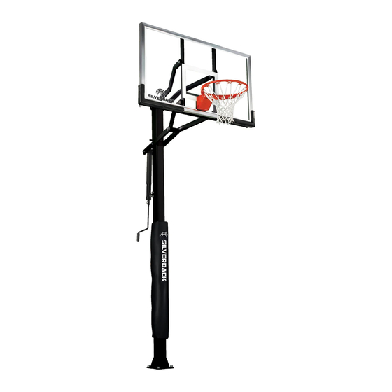
B5409W
SB60 - GHOST
BASKETBALL SYSTEM
2L-7968-00
©
2021 Escalade Sports
®
Advertisement

Related Manuals for ESCALADE SILVERBACK GHOST SB60


Summary of Contents for ESCALADE SILVERBACK GHOST SB60
- Page 1 6. Save these instructions and your proof of purchase (receipt) in the event that the manufacturer has to be contacted for replacement parts. Please Do Not Return This Product To The Store! ® Contact Escalade Sports customer service department at: 1-800-USA-GOAL Phone: Toll – Free !
-
Page 2: Safety Instructions
SAFETY INSTRUCTIONS FAILURE TO FOLLOW THESE WARNINGS MAY RESULT IN SERIOUS INJURY AND/OR PROPERTY DAMAGE. Owner must ensure that all players know and follow these rules for safe operation of the system. Owner must ensure that all players know and follow these rules for safe operation of the system. WARNING FAILURE TO FOLLOW THESE WARNINGS MAY R E S U LT I N S E R I O U S I N J U R Y A N D / O R... -
Page 3: Back Side
WARNING DO NOT DUNK ON THIS UNIT . DO NOT HANG FROM ANY PART OF THIS UNIT , INCLUDING THE BACKBOARD, RIM, SUPPORT BRACES OR NET. 4L-8152-01 (Affixed to Top Post on the front side) Bottom of upper pole must cover the above orange portion of this sticker (6”... - Page 4 3/8”-16 Nylon Insert Lock Nut (14 Pieces) 3/8-16 X 71/2” Hex Bolt (1 Piece) 1/2”-13 Nylon Insert Lock Nut (1 Piece) #10 X 1 1/8” (10 Pieces) 3/8-16 X 7” Hex Bolt (3 Pieces) 5/8” Thread Protector Cap (4 Pieces)
- Page 5 INSTALLATION TIMELINE Prior to anchor system and goal assembly, call utility services for location of underground utility lines before you dig. Vertical main post assembly is a two part process. PART 1 PART 2 ® Day 1. Complete Anchor System Installation Instructions. Day 5.
- Page 6 ASSEMBLY INSTRUCTIONS (Day 5) ASSEMBLY INSTRUCTIONS (Day 5) TOOLS REQUIRED FOR THE FOLLOWING STEPS TOOLS REQUIRED FOR THE FOLLOWING STEPS 1 - 15/16" Open end Wrench 1 - 15/16" Open end Wrench 1 - Phillips Screwdriver 1 - Phillips Screwdriver Be sure that the Be sure that the 1 - 15/16”...
- Page 7 NOTE: Self Drilling screws (#77) are used. Holes are SCREWS (#77) MUST BE INSTALLED TO POLE AS DESCRIBED only on outside Pole. User IN STEP 3. FAILURE TO INSTALL SCREWS COULD RESULT IN must insert screws through SERIOUS INJURY OR PROPERTY DAMAGE. BOTH POLES.
- Page 8 If not already pre-assembled, slide Plastic Actuator Sleeve (#15) over Steel Actuator (#16) and place Actuator Cap (#13) on top. Align holes in all 3 parts and slide P ivot Tube (#14) through holes in Actuator Cap (#13), Plastic Actuator Sleeve (#15) and Steel Actuator T ube (#16) until equal amounts stick out through both sides of actuator .
-
Page 9: Side View
Attach lower arms (#11) to Top Pole (#3), as shown in IMPORTANT! Nylon washers (#5) adequately space painted parts at all pivot points. Neglecting the use of Figure 7, using a hex bolt (#22), two flat washers (#18), these washers will result in rusted parts. two plastic washers (#5) and lock nut (#4). - Page 10 Attach long leg of Upper Arms (#6) to Top Pole (#3), as shown in Figure 9, using a bolt (#7), two flat washers (#18), two spacers (#8) and one lock nut (#4). Note: Tighten bolts snug but, do not over tighten. Board Arms must pivot freely Figure 9...
- Page 11 Locate hardware needed to mount pole to anchor bolts. You will need, eight flat washers (#37), four lock washers (#36), four hex nuts (#35) and four thread protectors (#34). NOTE: Do not remove the nuts #35 you installed in step 2 (pg. 5). PLACING THE POST ON THE ANCHOR SYSTEM REQUIRES AT LEAST FOUR CAPABLE ADULTS.
- Page 12 Slide Actuator Crank (#42) onto shaft on the bottom of Actuator (#16). Line up hole in shaft with hole in Actuator Crank and insert Pin (#41) to secure. See Figure 11. To aid in the assembly of the backboard, lower the backboard, by turning the Actuator Handle, until the lower arm makes contact with Stop Spacer (#10).
- Page 13 Figure 13 18. Mount Goal Assembly (#28) to Backboard, as shown in Figure 13, using four bolts (#49), four washers (#26), and four locknuts (#4). Tighten fasteners, but leave them loose enough to level rim. 19. Place a level across rim assembly and adjust rim until it is level.
- Page 14 Raise Backboard to 10 FT. regulation playing height. Measure from top of rim straight down to the playing surface. Using tape - mark the side of the steel actuator (#16) just under the plastic actuator sleeve (#15) at this 10 ft rim height.
- Page 15 Two adults are recommended for this step, one to level and one to adjust the bottom #35 nuts. If further leveling is required loosen top #35 nuts but do not loosen past the top of #39 “J” Bolt. DO NOT REMOVE NUTS #35 Place a level on pole and adjust bottom nuts #35 with a 15/16”...
- Page 16 OR OTHER CAUSES NOT ARISING OUT OF DEFECTS IN MATERIAL OR WORKMANSHIP . ® Subject to proper installation and normal Residential use, Escalade Sports warrants, subject to the limitations below, to the original retail ® purchaser all structural components of the Silverback System to be free of defects in material and workmanship for a period of Seven (7) years from the original purchase.
-
Page 17: Maintenance
SILVERBACK CARE INFORMATION - BACKBOARD - Items needed to clean backboard: 100% cotton soft cloth, (only) Glass Cleaner Clean backboard using a 100% Cotton soft cloth and glass cleaner. Clean glass as you would household windows. Strong cleansers will damage backboard and void warranty. - Page 18 (Pre-Installed) (Pre-Installed) Note: All #9 Caps (Pre-Installed) are Pre-Installed. , IN O RT , RI 2L-7968-00...
Need help?
Do you have a question about the SILVERBACK GHOST SB60 and is the answer not in the manual?
Questions and answers