Alfa Laval ThinkTop Instruction Manual
Digital, as-interface and devicenet
Hide thumbs
Also See for ThinkTop:
- Instruction manual (44 pages) ,
- Installation instruction (2 pages) ,
- Instruction manual (22 pages)

Subscribe to Our Youtube Channel
Related Manuals for Alfa Laval ThinkTop


Summary of Contents for Alfa Laval ThinkTop
- Page 1 Instruction Manual ® ThinkTop Digital, AS-Interface and DeviceNet Patented Sensor System Registered Design Registered Trademark ESE02952-EN3 2022-10 Original manual...
-
Page 3: Table Of Contents
5.6. Electrical connection, internal - AS-Interface ........... 5.7. Electrical connection, internal - DeviceNet ............. 6. Setup diagram ................6.1. ThinkTop setup- utilising local 'I' and 'II' keys ..........6.2. ThinkTop setup- utilising IR keypad ............. 6.3. ThinkTop quick setup guide .............. -
Page 4: Declarations Of Conformity
Declaration of of of Conformity Conformity Declaration Conformity The Designated Company Alfa Laval Kolding A/S, Albuen 31, DK-6000 Kolding, Denmark, +45 79 32 22 00 Company name, address and phone number Hereby declare that Top Unit for Valve Control and Indication Designation ThinkTop ®... - Page 5 Declaration of of of Conformity Conformity Conformity The Designated Company Alfa Laval Kolding A/S, Albuen 31, DK-6000 Kolding, Denmark, +45 79 32 22 00 Company name, address and phone number Hereby declare that Top Unit for Valve Control and Indication Designation ®...
-
Page 6: Safety
Never service the ThinkTop when the valve/actuator under pressure Never Never Never clean the ThinkTop using high pressure cleaning equipment Never Never Never use cleaning agents that will erode the exterior of the ThinkTop. Check with your cleaning agent supplier Never... -
Page 7: General Information
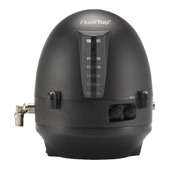
3 General information 3.1 ThinkTop at a glance The ThinkTop is designed to ensure optimum and reliable valve control in conjunction with Alfa Laval valves and is compatible with most PLC systems (Programmable Logic Controllers). The ThinkTop can be equipped with 0-3 solenoid valves. The solenoids are electrically controlled by the PLC system and, when activated, the compressed air is activating the air actuator. -
Page 8: Technical Specifications
Note! Supply voltage..... . . Must match the selected type of ThinkTop. Supply current: ..... . Max. 15 mA per sensor. - Page 9 4 Technical specifications T T T echnical echnical specifications echnical specifications specifications Up to 3 solenoid valves in each unit. Type 3/2 or 5/2 valve (only possible with one 5/2 valve) Air supply 300-900 kPa (3-9 bar) Filtered air, max. particles or dirt 5 µ...
-
Page 10: Thinktop Digital
Output signals from the sensor unit to the connected PLC. Nominal voltage: ....Must match the selected type of ThinkTop. Load current: ......Typically 50 mA, max. 100 mA . -
Page 11: Thinktop, As-Interface
ID1 code: F ID2 code: F Slave profile = S-7.F.F.F No. of of of slaves: slaves: slaves: AS-Interface specification 2.1 for max. 31 ThinkTop units on a single master/gateway Slave Slave Slave pr pr profile ofile ofile v v v .3.0 .3.0... - Page 12 4 Technical specifications AS- - - Interface Interface Interface bits bits assignment: bits assignment: assignment: For the AS-Interface version with 31 and 62 nodes, the following bit assignment will be used: DI 0 ........De-Energised position (closed position) DI 1 .
-
Page 13: Thinktop Devicenet
4 Technical specifications 4.4 ThinkTop DeviceNet DeviceNet featur featur es es es and and functionality functionality DeviceNet DeviceNet featur functionality Network size size Up to to to 63 63 nodes nodes nodes Network Network size Network length Selectable end-to-end network distance varies with speed... - Page 14 The EDS file can be downloaded from www.alfalaval.com by searching "ThinkTop" at the top of the main landing page. On the ThinkTop landing page, choose Documentation in the menu and find the EDS package. Alternatively, both the EDS file and...
- Page 15 Test conditions: One ThinkTop DeviceNet connected to the network with 1 input (on) and: No solenoids on 20 mA supply voltage 25 VDC 1 solenoid active (PWM) supply voltage 25 VDC 28 mA...
-
Page 16: Installation
Step Step Step 1 1 1 Always Always Always read the technical data carefully. Always ensure the ThinkTop is electrically connected by authorised personnel. Always Always Step 2 2 2 Step Step 1. Fit the air fittings on the actuator if not mounted. - Page 17 Install the air tubes with reference to the Air connections diagram on page 21 Step Step Step 6 6 6 Untighten the four screws and pull off the ThinkTop cover. Step Step 7a 7a Step 7a - Cable gland version 1.
- Page 18 5 Installation Step 8 8 8 Step Step Set up the ThinkTop (see chapter 6 Setup diagram). NOTE! NOTE! NOTE! The unit can be set up by the internal push buttons on the sersor board. To energise the valve, use manual hold override on the...
-
Page 19: Installation On Series 700 Valves
5 Installation 5.2 Installation on Series 700 valves Step Step Step 1 1 1 Installation on air actuators: 1. Remove the cover by loosening the four cover screws. 2. Separate the adapter from the base by loosening the three recess screws on top of the base. Step Step Step 2 2 2... - Page 20 5 Installation Step Step Step 4 4 4 Mount the base on the adapter in the necessary position (can be rotated 120° in both directions). Note that one of the screw towers on the adapter has a guide recess (see * on diagram).
-
Page 21: Air Connections
5 Installation 5.3 Air connections A Air out 1A B Air exhaust C Solenoid 3/2 or 5/2 D Air out 1B (5/2 port solenoid valve only) E Solenoid valves only 3/2 F Air in G Air out 3 H Air out 2 J Manual hold override K Air restriction (throttle function) air inlet/outlet... -
Page 22: Electrical Connection, Internal - Digital 24 Vdc
5 Installation 5.4 Electrical connection, internal - Digital 24 VDC Solenoid 1 Closed valve Solenoid 2 Open valve Solenoid 3 Seat-lift 1 Supply + Seat-lift 2 Supply - Status Solenoid com 12 NPN/PNP Jumper **) Eart- Earth 13 NPN/PNP Jumper **) 24 Seat-lift 1 “upper”... -
Page 23: Electrical Connection, Internal - As-Interface
5 Installation 5.6 Electrical connection, internal - AS-Interface ASI + (BN, brown) ASI - (BU, blue) 12 PWM Jumper **) Eart- Earth 13 PWM Jumper **) 24 Seat-lift 1 “upper” *) Solenoid common grey 25 Seat-lift 2 “lower” *) Solenoid 1, grey 26 Supply + *) Solenoid 2, grey Solenoid 3, grey... -
Page 24: Electrical Connection, Internal - Devicenet
5 Installation 5.7 Electrical connection, internal - DeviceNet Electrical Electrical Electrical connection connection connection DeviceNet 63 node Sensor board Terminal strip Power bus V- (Black) CAN_L (Blue) Drain (Bare) Bus cable CAN_H (White) Not Connected Power bus V+ (Red) Not connected Earth Earth Seat-lift 1 "upper"... -
Page 25: Setup Diagram
6 Setup diagram 6.1 ThinkTop setup- utilising local 'I' and 'II' keys General General General Default is: Step 2, tolerance is +/- 5 mm Step 3-8, disabled Timeout: A 60 sec. timeout is started as soon as any button(s) is released. - Page 26 6 Setup diagram...
- Page 27 6 Setup diagram T T T olerance olerance pr pr programs olerance ograms ograms Default Default Default No. 1 1 1 No. 2 2 2 No. 3 3 3 No. 4 4 4 (Used for self adjustment) MH Koltek Unique Mixproof Unique SSV SMP-EC (LKLA-T)
-
Page 28: Thinktop Setup- Utilising Ir Keypad
6 Setup diagram 6.2 ThinkTop setup- utilising IR keypad General General General Flashing LED means no value set. Steady LED means value set as shown. Default: Step 2, factory-set tolerance band +/- 5 mm Step 3-8, disabled D LED: Active during setup:... - Page 29 6 Setup diagram...
-
Page 30: Thinktop Quick Setup Guide
6 Setup diagram 6.3 ThinkTop quick setup guide V V V alve: alve: alve: Unique Unique Unique SSV SSV, , , SRC/ARC SRC/ARC SRC/ARC type type type NC NC (self (self - - - adjustment (self adjustment disabled) adjustment disabled) - Page 31 6 Setup diagram V V V alve: alve: alve: LKB LKB V V V alve alve alve (Butterfly) (Butterfly) NO (Butterfly) Push: - and wait until red LED flashes Push: Hold: - hold for 5 sec (clear all stored parameters) II 5s Push: (red + yellow LED)
-
Page 32: Fault Finding
- Removing a ThinkTop with self-adjust activated, will immediately generate an alarm condition! If the ThinkTop has to be removed - not because of a valve maintenance issue - but for another reason and you wish to store the data already adjusted, disable the self-adjust function before removing the ThinkTop and enable it again once the ThinkTop is back on the actuator. - Page 33 7 Fault finding Yellow steady: Yellow B Position B (open valve). Yellow steady: Position C (Seat lift 1-2 or external sensors). Yellow C Green steady: Solenoid valves energised. Green Note! Note! Note! LED lights have different functions during setup.
-
Page 34: Maintenance
Step Step Step 4 4 4 1. To dismantle the adapter (the lower part of the ThinkTop) from base (the middle part), unscrew the three screws 2. Turn the lower part clockwise slightly and pull 3. Replace adapter if necessary... -
Page 35: Assembly Of Thinktop
Step Step Step 5 5 5 To remove the sensor unit, untighten screw and pull out the sensor unit. 8.2 Assembly of ThinkTop Step 1 1 1 Step Step Place sensor unit in base and tighten screw (torque: 1 Nm). - Page 36 1. Replace solenoid valves (up to three) with new ones. 2. Tighten screws (0.2 Nm). Step Step Step 4 4 4 1. Replace the grey X-ring. 2. Replace cover of ThinkTop and tighten the four screws (0.6 Nm). Step Step Step 5 5 5 1. Replace the black X-ring.
-
Page 37: Dismantling And Assembling Series 700 Valves
8 Maintenance Read the instructions carefully. Handle scrap correctly. Always have spare X-rings to hand. 8.3 Dismantling and assembling Series 700 valves Step Step Step 1 1 1 1. Remove the cover by loosening the four cover screws. 2. Separate the adapter from the base by loosening the three recess screws on top of the base. - Page 38 8 Maintenance Read the instructions carefully. Handle scrap correctly. Always have spare X-rings to hand. Step Step Step 4 4 4 1. Mount the base on the adapter in the necessary position (can be rotated 120° in both directions). Note that one of the screw towers on the adapter has a guide recess (see * on drawing).
-
Page 39: Parts List
9 Parts list The items refer to the parts lists in the following sections 9.1 Diagrams for ThinkTop... -
Page 40: Thinktop
9 Parts list The items refer to the parts lists in the following sections 9.2 ThinkTop... - Page 41 9 Parts list The items refer to the parts lists in the following sections Parts Parts Parts list list list Pos. Denomination Shell complete Screw Washer Sensor board Solenoid valve (3/2) Solenoid valve (3/2 or 5/2) PT screw Base Special X-ring, grey Air fittings Blow-off valve Thread plug, PG7...
-
Page 43: Diagrams For Thinktop: Series 700
9 Parts list The items refer to the parts lists in the following sections 9.3 Diagrams for ThinkTop: Series 700... -
Page 44: Thinktop: Series 700
9 Parts list The items refer to the parts lists in the following sections 9.4 ThinkTop: Series 700... - Page 45 9 Parts list The items refer to the parts lists in the following sections Parts Parts Parts list list list Pos. Denomination Shell complete Screw Washer Sensor board Solenoid valve (3/2) Solenoid valve (3/2 or 5(2) PT screw Base Speciel X-ring, grey Air fittings Blow-off valve Thread plug, PG7...
- Page 46 © Alfa Laval Corporate AB This document and its contents is owned by Alfa Laval Corporate AB and protected by laws governing intellectual property and thereto related rights. It is the responsibility of the user of this document to comply with all applicable intellectual property laws. Without limiting any rights related to this document, no part of this document may be copied, reproduced or transmitted in any form or by any means (electronic, mechanical, photocopying, recording, or otherwise), or for any purpose, without the expressed permission of Alfa Laval Corporate AB.
Need help?
Do you have a question about the ThinkTop and is the answer not in the manual?
Questions and answers