Alfa Laval ThinkTop Digital Instruction Manual
As-interface and devicenet
Hide thumbs
Also See for ThinkTop Digital:
- Instruction manual (46 pages) ,
- Installation instruction (2 pages) ,
- Instruction manual (20 pages)

Related Manuals for Alfa Laval ThinkTop Digital


Summary of Contents for Alfa Laval ThinkTop Digital
- Page 1 Instruction Manual ® ThinkTop Digital, AS-Interface and DeviceNet 2050-0029 Patented Sensor System Registered Design Registered Trademark ESE02952-EN1 2016-10 Original manual www.sks-online.com www.sks-webshop.com...
- Page 2 www.sks-online.com www.sks-webshop.com...
-
Page 3: Table Of Contents
3.1. ThinkTop at a glance ................3.2. Recycling information ................4. Technical specifications ................4.1. ThinkTop common specifications ............... 4.2. ThinkTop Digital ................... 4.3. ThinkTop, AS-Interface ................4.4. ThinkTop DeviceNet ................5. Installation ....................5.1. Installation on air actuators .............. -
Page 4: Ec Declaration Of Conformity
1 EC Declaration of Conformity Revision of Declaration of Conformity 2009-12-29 The Designated Company Alfa Laval Kolding A/S Company Name Albuen 31, DK-6000 Kolding, Denmark Address +45 79 32 22 00 Phone No. hereby declare that Top Unit for Valve Control and Indication Designation ThinkTop®... -
Page 5: Safety
2 Safety This manual highlights unsafe practices and other important information are emphasised in this manual. Warnings are emphasised by means of special signs. All warnings in the manual are summarised on this page. Pay special attention to the instructions below in order to avoid severe personal injury or damage to the top unit are avoided. 2.1 Important information Always read the manual before using the top unit! WARNING... -
Page 6: General Information
3 General information 3.1 ThinkTop at a glance The ThinkTop is designed to ensure optimum and reliable valve control in conjunction with Alfa Laval valves and is compatible with most PLC systems (Programmable Logic Controllers). The ThinkTop can be equipped with 0-3 solenoid valves. The solenoids are electrically controlled by the PLC system and, when activated, the compressed air is activating the air actuator. -
Page 7: Technical Specifications
4 Technical specifications 4.1 ThinkTop common specifications Sensor System Unique “No Touch” sensor system with no mechanical sensor adjustments. A magnet (indication pin) is mounted on the valve stem and the translatory change in the magnetic field vectors are detected by the sensor board with a measuring accuracy of ±... - Page 8 4 Technical specifications Technical specifications Up to 3 solenoid valves in each unit. Type 3/2 or 5/2 valve (only possible with one 5/2 valve) Air supply 300-900 kPa (3-9 bar) Filtered air, max. particles or dirt 5 µ 5-5 mg/m Max.
-
Page 9: Thinktop Digital
4 Technical specifications 4.2 ThinkTop Digital Power Supply The ThinkTop is designed to be a part of the PLC’s Input/Output (I/O) system. It should be supplied from the same protected power supply as the other I/O devices. The I/O power supply should not be used for other kinds of load. -
Page 10: Thinktop, As-Interface
4 Technical specifications 4.3 ThinkTop, AS-Interface Feedback signals Power Supply The power supply to the complete unit is taken from the AS-Interface loop. The unit is reverse polarity protected. Supply voltage: ..... . 29.5 - 31.6 VDC Normal current consumption sensor board . - Page 11 4 Technical specifications AS-Interface bits assignment: For the AS-Interface version with 31 and 62 nodes, the following bit assignment will be used: DI 0 ........De-Energised position (closed position) DI 1 .
-
Page 12: Thinktop Devicenet
4 Technical specifications 4.4 ThinkTop DeviceNet DeviceNet features and functionality Up to 63 nodes Network size Network length Selectable end-to-end network distance varies with speed Baud Rate Distance 125 Kbps 500 m (1,640 ft) 250 Kbps 250 m (820 ft) 500 Kbps 100 m (328 ft) Data packets... - Page 13 4 Technical specifications DeviceNet interface Baud rates: 125K, 250K and 500K. Polling I/O slave messaging. Poll: 1 bytes. 1 bytes = Input/outputs and alarms (class 4). Node address Range: 0-63. Default slave address: 63. Power supply The power supply to the complete unit is taken from the DeviceNet. Supply voltage: .
- Page 14 4 Technical specifications ThinkTop DeviceNet attribute list Path Raw data Name Attributes R/W/CS data len. type Release DNET 4.6 “poll” Class Inst dec. hex. Valve value Byte Valve command Byte ThinkTop DeviceNet attribute list Name Eng. Units Conv. Bit maps/data mult.
-
Page 15: Installation
5 Installation 5.1 Installation on air actuators Step 1 Always read the technical data carefully. Always ensure the ThinkTop is electrically connected by authorised personnel. Step 2 1. Fit the air fittings on the actuator if not mounted. 2. Fit the activator stem (magnet) and tighten carefully with a spanner. - Page 16 5 Installation Step 5 Install the air tubes with reference to the Air connections diagram on page 19 2050-0018 Step 6 Untighten the four screws and pull off the ThinkTop cover. 2050-0019 Step 7a - Cable gland version 1. Install cable (if not present) through the cable gland. 2.
-
Page 17: Installation On Series 700 Valves
5 Installation 5.2 Installation on Series 700 valves Step 1 Installation on air actuators: 1. Remove the cover by loosening the four cover screws. 2. Separate the adapter from the base by loosening the three recess screws on top of the base. 2050-0023 Step 2 1. - Page 18 5 Installation Step 4 Mount the base on the adapter in the necessary position (can be rotated 120° in both directions). Note that one of the screw towers on the adapter has a guide recess (see * on diagram). 2050-0037 www.sks-online.com www.sks-webshop.com...
-
Page 19: Air Connections
5 Installation 5.3 Air connections A Air out 1A B Air exhaust C Solenoid 3/2 or 5/2 D Air out 1B (5/2 port solenoid valve only) E Solenoid valves only 3/2 F Air in G Air out 3 H Air out 2 J Manual hold override K Air restriction (throttle function) air inlet/outlet 2050-0022... -
Page 20: Electrical Connection, Internal - Digital 24 Vdc
5 Installation 5.4 Electrical connection, internal - Digital 24 VDC Solenoid 1 Closed valve Solenoid 2 Open valve Solenoid 3 Seat-lift 1 Supply + Seat-lift 2 Supply - Status Solenoid com 12 NPN/PNP Jumper **) Earth Earth 13 NPN/PNP Jumper **) 24 Seat-lift 1 “upper”... -
Page 21: Electrical Connection, Internal - As-Interface
5 Installation 5.6 Electrical connection, internal - AS-Interface ASI + (BN, brown) ASI - (BU, blue) 12 PWM Jumper **) Earth Earth 13 PWM Jumper **) Solenoid common grey 24 Seat-lift 1 “upper” *) 25 Seat-lift 2 “lower” *) Solenoid 1, grey Solenoid 2, grey 26 Supply + *) 27 Supply - *) -
Page 22: Electrical Connection, Internal - Devicenet
5 Installation 5.7 Electrical connection, internal - DeviceNet Electrical connection DeviceNet 63 node Sensor board Terminal strip Power bus V- (Black) CAN_L (Blue) Drain (Bare) Bus cable CAN_H (White) Not Connected Power bus V+ (Red) Not connected Seat-lift 1 "upper" Earth Earth Incoming signals from external... -
Page 23: Setup Diagram
6 Setup diagram 6.1 ThinkTop setup- utilising local ’I’ and ’II’ keys General Default is: Step 2, tolerance is +/- 5 mm Step 3-8, disabled Timeout: A 60 sec. timeout is started as soon as any button(s) is released. On timeout the setup is exited with no changes saved. Flashing LED means no value set. - Page 24 6 Setup diagram Enter Setup Step 1 - Save and Exit Exit no change accepted Next step Step 2 - Setup valve type Default No 1 No 2 No 3 No 4 +/- 5mm Next step 4 II Next step Step 3 - Set closed position Default Position stored...
- Page 25 6 Setup diagram Tolerance programs Default No. 1 No. 2 No. 3 No. 4 (Used for self adjustment) MH Koltek Unique Mixproof Unique SSV SMP-EC (LKLA-T) SMP-SC Spillage free Unique Mixproof PMO Unique SSV NO Series 700 SRC-PV Unique Mixproof Curd shut off Unique Mixproof CP3 Unique Mixproof LP...
-
Page 26: Thinktop Setup- Utilising Ir Keypad
6 Setup diagram 6.2 ThinkTop setup- utilising IR keypad General Flashing LED means no value set. Steady LED means value set as shown. Default: Step 2, factory-set tolerance band +/- 5 mm Step 3-8, disabled D LED: Active during setup: Flashing in step 1 Steady in all other steps Or during operations, error condition:... - Page 27 6 Setup diagram Enter Setup Step 1 - Save and Exit Exit no change accepted Next step Step 2 - Setup valve type Default No 1 No 2 No 3 No 4 +/- 5mm Reset unit Next step Step 3 - Set closed position Default Position stored Next...
-
Page 28: Thinktop Quick Setup Guide
6 Setup diagram 6.3 ThinkTop quick setup guide Valve: Unique SSV, SRC/ARC type NC (self-adjustment disabled) - and wait until red LED flashes Push: Push: - hold for 5 sec (clear all stored parameters) Hold: II 5s Push: (red + yellow LED) Push: (red + yellow + green LED) Push:... - Page 29 6 Setup diagram Valve: LKB Valve (Butterfly) NO Push: - and wait until red LED flashes Push: Hold: II 5s - hold for 5 sec (clear all stored parameters) Push: (red + yellow LED) Push: (red + yellow + green LED) Push: Activate - to close valve...
-
Page 30: Fault Finding
7 Fault finding 7.1 Fault finding and LEDs The information below explains the meaning of the LEDs’ indications for fault finding in connection with the operation of the ThinkTop. Red flashing: Unit in setup mode or internal software fault. If internal software fault is present, re-programme unit. - Page 31 7 Fault finding Yellow steady: Yellow B Position B (open valve). Yellow steady: Position C (Seat lift 1-2 or external sensors). Yellow C Green steady: Solenoid valves energised. Green Note! LED lights have different functions during setup. www.sks-online.com www.sks-webshop.com...
-
Page 32: Maintenance
8 Maintenance Read the instructions carefully. Handle scrap correctly. Always have spare X-rings to hand. 8.1 Dismantling ThinkTop Step 1 1. Untighten the two Allen screws and remove the ThinkTop from the actuator 2. Pull out X-ring (19) and replace it Step 2 1. -
Page 33: Assembly Of Thinktop
8 Maintenance Read the instructions carefully. Handle scrap correctly. Always have spare X-rings to hand. Step 5 To remove the sensor unit, untighten screw and pull out the sensor unit. TD 800-256 8.2 Assembly of ThinkTop Step 1 Place sensor unit in base and tighten screw (torque: 1 Nm). TD 800-257 Step 2 1. - Page 34 8 Maintenance Read the instructions carefully. Handle scrap correctly. Always have spare X-rings to hand. Step 3 1. Replace solenoid valves (up to three) with new ones. 2. Tighten screws (0.2 Nm). TD 800-264 Step 4 1. Replace the grey X-ring. 2.
-
Page 35: Dismantling And Assembling Series 700 Valves
8 Maintenance Read the instructions carefully. Handle scrap correctly. Always have spare X-rings to hand. 8.3 Dismantling and assembling Series 700 valves Step 1 1. Remove the cover by loosening the four cover screws. 2. Separate the adapter from the base by loosening the three recess screws on top of the base. - Page 36 8 Maintenance Read the instructions carefully. Handle scrap correctly. Always have spare X-rings to hand. Step 4 1. Mount the base on the adapter in the necessary position (can be rotated 120° in both directions). Note that one of the screw towers on the adapter has a guide recess (see * on drawing).
-
Page 37: Parts List
9 Parts list The items refer to the parts lists in the following sections 9.1 Diagrams for ThinkTop 225 mm (9”) TD 800-267 2053-0000 ø137 mm (5½”) TD 800-262 www.sks-online.com www.sks-webshop.com... -
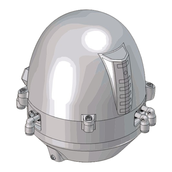
Page 38: Thinktop
9 Parts list The items refer to the parts lists in the following sections 9.2 ThinkTop www.sks-online.com www.sks-webshop.com... - Page 39 9 Parts list The items refer to the parts lists in the following sections Parts list Pos. Denomination Shell complete Screw Washer Sensor board Solenoid valve (3/2) Solenoid valve (3/2 or 5/2) PT screw Base Special X-ring, grey Air fittings Blow-off valve Thread plug, PG7 Cable gland, PG11 (or optional...
- Page 40 www.sks-online.com www.sks-webshop.com...
-
Page 41: Diagrams For Thinktop: Series 700
9 Parts list The items refer to the parts lists in the following sections 9.3 Diagrams for ThinkTop: Series 700 225 mm (9”) TD 800-269 2053-0000 ø137 mm (5½”) TD 800-271 www.sks-online.com www.sks-webshop.com... -
Page 42: Thinktop: Series 700
9 Parts list The items refer to the parts lists in the following sections 9.4 ThinkTop: Series 700 www.sks-online.com www.sks-webshop.com... - Page 43 9 Parts list The items refer to the parts lists in the following sections Parts list Pos. Denomination Shell complete Screw Washer Sensor board Solenoid valve (3/2) Solenoid valve (3/2 or 5(2) PT screw Base Speciel X-ring, grey Air fittings Blow-off valve Thread plug, PG7 Cable gland, PG11...
- Page 44 © Alfa Laval Corporate AB This document and its contents is owned by Alfa Laval Corporate AB and protected by laws governing intellectual property and thereto related rights. It is the responsibility of the user of this document to comply with all applicable intellectual property laws. Without limiting any rights related to this document, no part of this document may be copied, reproduced or transmitted in any form or by any means (electronic, mechanical, photocopying, recording, or otherwise), or for any purpose, without the expressed permission of Alfa Laval Corporate AB.
Need help?
Do you have a question about the ThinkTop Digital and is the answer not in the manual?
Questions and answers