Alfa Laval ThinkTop Basic Instruction Manual
As-interface v.3.0
Hide thumbs
Also See for ThinkTop Basic:
- Instruction manual (46 pages) ,
- Installation instruction (2 pages) ,
- Instruction manual (18 pages)

Related Manuals for Alfa Laval ThinkTop Basic


Summary of Contents for Alfa Laval ThinkTop Basic
- Page 1 Instruction Manual ® ThinkTop Basic AS-Interface v.3.0 (62 nodes) 29.5 - 31.6 VDC TD 800-242_1 Patented Sensor System Registered Design Registered Trademark ESE01516-EN3 2014-12 Original manual...
-
Page 3: Table Of Contents
2.1. Important information ................2.2. Warning signs ..................2.3. Safety precautions ................3. General information ................... 3.1. ThinkTop Basic AS-Interface in general ............4. Technical specifications ................4.1. ThinkTop Basic AS-Interface ..............5. Installation ....................5.1. Installation on air actuators .............. -
Page 4: Ec Declaration Of Conformity
1 EC Declaration of Conformity The Designated Company Alfa Laval Kolding A/S Company Name Albuen 31, DK-6000 Kolding, Denmark Address +45 79 32 22 00 Phone No. hereby declare that Top Unit for Valve Control and Indication Designation ThinkTop® Basic AS-Interface... -
Page 5: Safety
WARNING Indicates that special procedures must be followed to avoid serious personal injury. CAUTION Indicates that special procedures must be followed to avoid damage to the ThinkTop Basic AS-Interface. NOTE Indicates important information to simplify or clarify procedures. 2.2 Warning signs... -
Page 6: General Information
3 General information 3.1 ThinkTop Basic AS-Interface in general The ThinkTop Basic AS-Interface is designed to ensure valve control in conjunction with Alfa Laval sanitary valves and it is compatible with all major PLC systems (Programmable Logic Controller). The ThinkTop Basic AS-Interface can be equipped with 0-3 solenoid valves. The solenoids are electrically controlled via the AS-Interface and when activated the compressed air is activating the air actuator. -
Page 7: Technical Specifications
10. Terminals 20. N/A TD 800-267 TD 800-267 Type: Alfa Laval “No Touch” System. For wire connections: See 5.3 Electrical connection, internal“. Features - Easy and simple set-up, using locally pushbottons. - No manual sensor adjustments at all. - No sensor "movements" due to vibrations. - Page 8 Supply voltage: ..... . 29.5 - 31.6 VDC Typical power consumption ThinkTop Basic AS-Interface Test conditions = One ThinkTop Basic AS-Interface connected with 1 feedback active (on) and: No solenoids on...
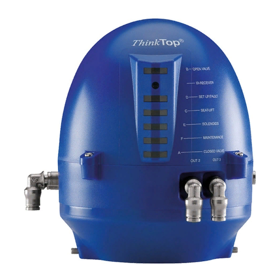
- Page 9 4 Technical specifications ThinkTop Basic AS-Interface Visual Indications LED Indications LED A “Energized” (Yellow) LED A LED B LED B “Setup/Fault” (Red) LED C LED C “Solenoid” (Yellow) “De-Energized" (Green) LED D LED D TD 800-030_1 Technical specifications solenoid valves Internal connections Terminals for wire connection of the solenoids mounted internally in the control head.
- Page 10 Type 1 input requirements EN 61131-2 EMC Directive 2004/108/EF EN 61000-6-3, EN 61000-6-2 AS-Interface Version 3.0*) EN50295 UL/CSA 10-30 VDC, Class 2 input, 45 mA max. output UL 508-E203255 *) Max. 62 ThinkTop Basic AS-Interface units on a single master/gateway.
-
Page 11: Installation
(A). Note: The threaded plate (B) is only used for the SRC and SMP valve types. TD 800-011_2 Step 3 1. Place the ThinkTop Basic AS-Interface on top of the actuator. 2. Make sure X-ring is mounted. - Page 12 2. Tighten the two Allen screws carefully (1.50 Nm). 3. Turn the actuator to have LEDs in a front view. Step 5 Fit the ø6 mm (1/4”) air tubes to ThinkTop Basic AS-Interface . (see drawing “Air connections” page 13). Step 6 Fit the air tubes to the actuator (see drawing “Air connections”...
-
Page 13: Air Connections
Make sure the cable gland is completely tightened. TD 800-159 Step 10 Set up the ThinkTop Basic AS-Interface (see chapter 6 Setup diagram). NOTE! The unit can be set up by internal push bottons on sensor board. To energize the valve, use manual hold override on the solenoids valve or be in radio contact with the control room. -
Page 14: Electrical Connection, Internal
5 Installation 5.3 Electrical connection, internal Electrical connections, internal 1. ASI + 2. ASI - 3. PWM jumper 4. PWM jumper 5. Solenoid common, internal connection (Brown) 6. Solenoid # 1, internal connection (Blue) 7. Solenoid # 2, internal connection (Blue) 8. -
Page 15: Setup Diagram
ThinkTop Basic Digital and AS-Interface A printable “one page” version of ThinkTop Basic setup diagram is available on the Alfa Laval website and can easily be found be typing the document name “ThinkTop Basic setup diagram” in the searh field. -
Page 16: Maintenance
2. Remove solenoid valves (up to three) and replace them with new ones. TD 800-235 Step 4 1. To dismantle the adapter (the lower part of the ThinkTop Basic AS-Interface) from base (the middle part), unscrew the three screws. 2. Turn the lower part a little clockwise and pull. -
Page 17: Assembling The Thinktop
7 Maintenance Study the instructions carefully. Handle scrap correctly. Always keep spare X-rings in stock. Step 5 To remove the sensor unit untighten screw and pull out the sensor unit. TD 805-004 ® 7.2 Assembling the ThinkTop Step 1 Place sensor unit in base and tighten screw (torque: 1 Nm). TD 805-005 Step 2 1. - Page 18 1. Replace solenoid valves (up to three) with new ones. 2. Tighten screws (0.2 Nm). TD 800-234 Step 4 1. Replace the grey X-ring. 2. Replace cover of ThinkTop Basic AS-Interface and tighten the four screws (0.6 Nm). TD 805-007 Step 5 1. Replace the black X-ring.
-
Page 19: Parts List And Service Kits
8 Parts list and service kits The drawings show ThinkTop Basic AS-Interface v.3.0 (62 nodes) 29.5 - 31.6 VDC. The items refer to the parts lists in the following sections 8.1 Drawings for ThinkTop Basic AS-Interface AS-Interface (+) AS-Interface (-) -
Page 20: Thinktop Basic As-Interface
8 Parts list and service kits The drawings show ThinkTop Basic AS-Interface v.3.0 (62 nodes) 29.5 - 31.6 VDC. The items refer to the parts lists in the following sections 8.2 ThinkTop Basic AS-Interface TD 805-001... - Page 21 8 Parts list and service kits The drawings show ThinkTop Basic AS-Interface v.3.0 (62 nodes) 29.5 - 31.6 VDC. The items refer to the parts lists in the following sections Parts list Pos. Denomination Shell complete Screw Washer Sensor board...
- Page 22 © Alfa Laval Corporate AB This document and its contents is owned by Alfa Laval Corporate AB and protected by laws governing intellectual property and thereto related rights. It is the responsibility of the user of this document to comply with all applicable intellectual property laws. Without limiting any rights related to this document, no part of this document may be copied, reproduced or transmitted in any form or by any means (electronic, mechanical, photocopying, recording, or otherwise), or for any purpose, without the expressed permission of Alfa Laval Corporate AB.
Need help?
Do you have a question about the ThinkTop Basic and is the answer not in the manual?
Questions and answers