Advertisement
Quick Links
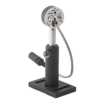
Operating Manual PDA500 - Switchable Gain, Amplified GaAsP Detector
Description:
The PDA500 is an amplified, switchable-gain, GaAsP detector designed for detection of light signals from DC to 200
kHz. A five-position rotary switch allows the user to vary the gain in 10 dB steps. A buffered output drives a 50Ω load
impedance up to 5 volt. The PDA500 housing includes a removable threaded coupler that is compatible with any
number of Thorlabs 1" threaded accessories. This allows convenient mounting of external optics, light filters
apertures, as well as providing an easy mounting mechanism using the Thorlabs cage assembly accessories.
The PDA500 has an 8-32 tapped mounting hole with a 0.25" mounting depth and includes a 120VAC power AC/DC
supply. The PDA500-EC has a M4 tapped mounting hole and includes A 230VAC AC/DC power supply.
Specifications:
Detector
Detector
Active Area
Response
Peak Response
Bandwidth
NEP (640nm, 0dB)
NEP (640nm, 10dB)
NEP (640nm, 20dB)
NEP (640nm, 30dB)
NEP (640nm, 40dB)
1
Output Voltage(50Ω)
1.
Output voltage
1
Output Impedance
1.
Load Impedance
Gain Steps
Gain Switch
On / Off Switch
Output
Damage Threshold
Optical Head Size
Weight
Accessories
Storage Temp
Operating Temp
AC Power Supply
Input Power
Note 1: The PDA500 has a 50Ω series terminator resistor (i.e. in series with amplifier output). This forms a voltage
divider with any load impedance (e.g. 50Ω load divides signal in half).
Setup
•
Unpack the optical head, install a Thorlabs TR-series ½" diameter post into the 8-32 (M4 on -EC version) tapped
hole on the bottom of the head, and mount into a PH-series post holder. Note: Do not install a mounting post
more than ¼" into the housing. This will damage the unit.
•
Plug the 5-pin DIN plug on the power supply provided with the PDA500 into the mating jack on the PDA500.
•
Plug the power supply into an 50-60Hz, 100-120VAC outlet (220-240VAC for -EC version).
PO Box 366, 435 Route 206N, Newton, NJ 07860
Ph (973) 579-7227, Fax (973) 383-8406, http://www.thorlabs.com
GaAsP
0 dB Setting
1.3 x 1.3 mm
300 to 680 nm
0.3 A/W @ 640 nm
DC to 150kHz
-12
W/√ √ √ √ Hz
60 x 10
W/√ √ √ √ Hz
-12
10 dB Setting
20 x 10
-12
W/√ √ √ √ Hz
9 x 10
-12
W/√ √ √ √ Hz
6 x 10
W/√ √ √ √ Hz
-12
4 x 10
0 to 5V
0 to 10V
20 dB Setting
50 ohms
Hi -Z to 50 ohms
0, 10, 20, 30, 40 dB
5-Pos Rotary
Toggle
BNC
100mW CW
30 dB Setting
2
0.5J/cm
10ns PW
φ φ φ φ 1.5" x 0.79"
60 grams
SM1T1 Coupler
-20 to 80° ° ° ° C
-10 to 60° ° ° ° C
40 dB Setting
AC - DC Converter
100-120VAC,
(220-240VAC-EC
version)
50-60Hz, 5W
2922-D02 Rev C 8/2/00
Performance
1
Transimpedance Gain
1
Trans. Gain (50Ω)
Bandwidth
Noise (RMS)
Offset
-5 mV
1
Transimpedance Gain
1
Trans. Gain (50Ω)
Bandwidth
Noise (RMS)
Offset
-5 mV
1
Transimpedance Gain
1
Trans. Gain(50Ω)
Bandwidth
Noise (RMS)
Offset
-10 mV
1
Transimpedance Gain
1
Trans. Gain (50Ω)
Bandwidth
Noise (RMS)
Offset
-20 mV
1
Transimpedance Gain
1
Trans. Gain(50Ω)
Bandwidth
Noise (RMS)
Offset
-100 mV
Page 1of 3
min
typical
4
1.5 x 10
V/A
4
0.75 x 10
V/A
150 kHz
< 100 µ µ µ µ V
4.5 mV
15 mV
4
4.7 x 10
V/A
4
2.35 x 10
V/A
150 kHz
130 µ µ µ µ V
5 mV
15 mV
5
1.5 x 10
V/A
5
0.75 x 10
V/A
150 kHz
170 µ µ µ µ V
6.5 mV
20 mV
5
4.7 x 10
V/A
5
2.35 x 10
V/A
100kHz
250 µ µ µ µ V
11 mV
50 mV
6
1.5 x 10
V/A
6
0.75 x 10
V/A
45kHz
400 µ µ µ µ V
25 mV
100 mV
max
Advertisement

Related Manuals for THORLABS PDA500


Summary of Contents for THORLABS PDA500
- Page 1 -100 mV 25 mV 100 mV Note 1: The PDA500 has a 50Ω series terminator resistor (i.e. in series with amplifier output). This forms a voltage divider with any load impedance (e.g. 50Ω load divides signal in half). Setup •...
- Page 2 The maximum output of the PDA500 is 10 volts (for high impedance loads). Adjust the gain so that the measured signal level out of the PDA500 is below 10 volts (5 volts with a 50Ω load) to avoid saturation. If necessary, use external neutral density filters to reduce the input light level.
- Page 3 Maintaining the PDA500 There are no serviceable parts in the PDA500 optical head or power supply. The housing can be cleaned by wiping with a soft damp cloth. The window of the detector should only be cleaned using optical grade wipes. If you suspect a problem with your PDA500 please call Thorlabs and an engineer will be happy to assist you.
Need help?
Do you have a question about the PDA500 and is the answer not in the manual?
Questions and answers