
Subscribe to Our Youtube Channel
Related Manuals for Nipro PHOENIX ONE


Summary of Contents for Nipro PHOENIX ONE
- Page 1 Operator´s Manual Reverse Osmosis TYPE: PHOENIX ONE Date: 13.01.2021 Version: 6 Written by:Rüdiger Tille...
- Page 2 For the reverse osmosis type Phoenix One, conformity according to 0297 EC directives is declared Foreword This Operator’s Manual includes all information required for the installation and operation for the reverse osmosis model Phoenix One. Please keep this Operator’s Manual readily available and near the unit.
-
Page 3: Water Quality
The scope of delivery includes the following parts: ▪ 1 reverse osmosis ▪ 1 connection set 1.3 Unit combinations The unit model Phoenix DS may be combined with the following devices: Hot cleaning system Phoenix One + Hot cleaning system Phoenix One +FH... -
Page 4: Accessories And Consumables
Version 6| 13.01.2021 Page 4 1.4 Accessories and Consumables ▪ 1 Prefilter 20“ 10µm 1.5 Notes for the Operator The operator is responsible for: Competent and intended operation Compliance with work safety and accident prevention provisions Technical instruction of operating personnel 1.6 Laws and Standards The following laws and standards are adhered to: Council Directive 93/42 EEC Medical Devices... -
Page 5: Transport And Storage
Version 6| 13.01.2021 Page 5 1.8 Transport and Storage Protect unit against frost and moisture Protect against strong jolting and collisions. Only move unit upright and with an appropriate lift. 1.9 Model Plate Attention, take note of accompanying documents CE mark with the number of the notified body. - Page 6 1.11 Shutdown If a unit is shutdown for more than 5 days, conservation will be necessary. Please contact Nipro Pure Water before performing conservation. 1.12 Disposal Regarding the WEEE guidelines of the European Union, the disposal of electronic devices and electronic sub-assemblies and parts into the general garbage is not lawful.
- Page 7 Spare parts list ▪ Technical manual If the system is operated in combination with the hot cleaning system Phoenix One + or hot cleaning system Phoenix One + FH, an extension to these operating instructions is available. 1.14 Duration of usage...
-
Page 8: Intended Operation
The device has pressurized parts. If the temperature sensor fails, the temperature in the permeate can increase. (Max 60°C) The water treatment system Phoenix One may only be used for permeate supply of dialysis devices, which have a temperature measurement (permeate temperature). - Page 9 Version 6| 13.01.2021 Page 9 The device has no direct patient contact and no patient application part. 2.1 Contraindications / side effects None...
-
Page 10: Risk Assessment
13.01.2021 Page 10 3 Safety 3.1 Risk Assessment There will be no dangers associated with the reverse osmosis model Phoenix One D if the operating instructions are followed. The device can automatically start by way of an auto-start. 3.2 EMC The device was developed and tested in accordance with current standards. -
Page 11: Technical Data
G 1” external Water feed Permeate connection TriClamp d50,5 DIN Drain HT 50 Electrical data Phoenix ONE Supply voltage 400 V, 3 Phases, 50 Hz 400 V, 3 Phases, 60 Hz Automat 16 A-K, Fi ΔI Automat 16 A-K, Fi ΔI Fuse... - Page 12 Version 6| 13.01.2021 Page 12 Display system Conductivity 0-1000 µS/cm ±5% Pressure sensor 0-20 bar ±5% Water meter 1impl/l ±1% Flow 0-3000 l/h ±1% Ambient temperature Storage / transport 1-40°C Operation 10-35°C Relative humidity < 90% at 20°C not condensing Air pressure 795-1062 hPa Size...
- Page 13 5 Description of the device...
- Page 14 Version 6| 13.01.2021 Page 14 5.1 Flow-Chart 1 Water meter 2 Membrane valve input 3 Fine filter 4 Float valve 5 Dry-run protection 6 Booster pump (Pressure 10-13 bar) 7 Pressure sensor pump pressure 8 Reverse osmosis membrane 9 Flow display Permeate 10 Temperature sensor permeate 11 Conductivity probe 12 Pressure sensor Permeate...
- Page 15 Version 6| 13.01.2021 Page 15 5.2 Operation Sequence Permeate Production. Untreated water flow the main through the water line (1) and the fine filter (3) into the break tank. The float valve (4) mounted in the break tank regulates the water level in the tank. The booster pump (6) draws the water out of the tank and then presses it into the reverse osmosis membrane (8).
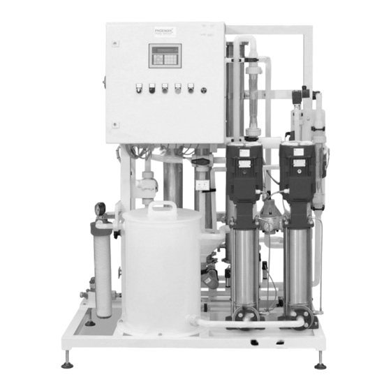
- Page 16 Version 6| 13.01.2021 Page 16 Components Through flow display Permeate back flow Main switch Through flow display Permeate flow Ball valve Permeat to drain Pressure retention valve Concentrate valve Prefilter Break tank Booster pumps DIN EN 1717...
-
Page 17: Installation
Version 6| 13.01.2021 Page 17 6 Installation The installation must be conducted by the manufacturer or by personnel trained and authorized by the manufacturer. 6.1 Environmental Conditions Conditions for the osmosis room: ▪ Relative air moisture < 90% at 20°C non-condensing ▪... -
Page 18: Electrical Installation
Version 6| 13.01.2021 Page 18 6.3 Electrical installation The installation may only be performed by a qualified electrician. The system must be supplied by a permanent connection, connectors are not valid. The disconnection via the main switch at the control cabinet. Connection box Main switch. -
Page 19: Installation Plan (Example)
Version 6| 13.01.2021 Page 19 Installation plan (Example) Local water works regulations and DIN EN 1717 must be followed. The water pre-treatment must be adapted to the local potable water quality. -
Page 20: Operation
Version 6| 13.01.2021 Page 20 7 Operation 7.1 Control Panel Keyboard for settings and call up operation values Display Device Start Control light unit in Devıce Stop operation Horn off Switch to manual Horn operation (emergency operation) Umschaltung auf Handbetrieb (Notbetrieb) Device Start Button... -
Page 21: Emergency Operation
Version 6| 13.01.2021 Page 21 7.2 Emergency operation Only use emergency operation if the automatic function fails. Have device repaired as soon as possible. Attention! There is no monitoring of the water inflow during the emergency operation. Therefore a continuous water inflow has to be guaranteed. Absent water causes the destruction of the pump. -
Page 22: Manual On / Off
Version 6| 13.01.2021 Page 22 7.3 Manual On / Off Press the green button to start the device. The green light will turn on. Press the red button to stop the device. The green light will turn off. -
Page 23: Quick Access Keys
Version 6| 13.01.2021 Page 23 7.4 Quick access keys MAIN MENU Info Display Conductivity Program selection Report list RO start = back Clean discard permeate Main menu (press for 5 seconds) To start the selected program, the green start button must be pressed. The device will start shortly after. - Page 24 Version 6| 13.01.2021 Page 24 7.5 Main menu MAIN MENU To call up main menu press the Info button for 5 seconds MAIN MENU Call up the info menu. See section Enter menu info Info Enter MAIN MENU Call up the notification menu. See Enter section menu notifications Notification...
- Page 25 Version 6| 13.01.2021 Page 25 7.6 Menu Info INFO Time MAIN MENU Info Enter INFO Display current date and time Enter Enter Time Display mode: INFO Unit ON Enter Unit OFF Mode Clean INFO Display: Permeate temperature = back Enter Temperatures Display: = browse...
- Page 26 Version 6| 13.01.2021 Page 26 7.7 Menu Notification INFO Time MAIN MENU Notification Enter Enter Display all notifications and alarms with time and date NOTIFICATIONS Enter Notification list E.g. water shortage 21.08.04 6:30 = back Displays all actions with time and date NOTIFICATIONS Enter Action list...
- Page 27 Version 6| 13.01.2021 Page 27 7.8 Menu Statistics MAIN MENU Statistics MAIN MENU Statistics Enter Enter Display: STATSTICS Total hours of operation Enter Hours of Hours of operation ON operation Hours of operation pump 06 Hours of operation pump 31 = back = browse...
-
Page 28: Menu Functions
Version 6| 13.01.2021 Page 28 7.9 Menu Functions MAIN MENU Funktionen MAIN MENU Functions Enter Enter FUNCTIONS Set date ane time Enter Set clock FUNCTIONS Changeover between the first and the Enter second pump can be done here Pumps = back FUNCTIONS The start and stop times for the reverse Enter... -
Page 29: Set Clock
Version 6| 13.01.2021 Page 29 7.10 Set clock MAIN MENU Functins MAIN MENU Functions Enter Enter TIMES Fr 12.10.2004 Enter Set clock 11:25:01 Press for 3 seconds Fr 12.10.2004 11:25:01 Move cursor Set time/ date Enter MAIN MENU Info... - Page 30 Version 6| 13.01.2021 Page 30 7.11 Timer...
-
Page 31: Maintenance And Cleaning
Version 6| 13.01.2021 Page 31 8 Maintenance and cleaning 8.1 External Cleaning A slightly dampened, lint-free cloth can be used to remove dirt stains and dust from pipes and other surfaces Do not clean the device with solvents. Stains from softening salts or disinfectants must be removed immediately. -
Page 32: Maintenance Intervals
Version 6| 13.01.2021 Page 32 8.2 Maintenance Intervals No service or maintenance work may be carried out during treatment. Measure period Notes user Change pre-filter 2 months or If the filter shows user after pressure discoloration, a drop> 1bar change must be performed as well Fill salt at softener Daily... -
Page 33: Prefilter Replacement
Version 6| 13.01.2021 Page 33 8.3 Prefilter Replacement Stop the device by pressing the red button. Close the membrane valve (2) by turning it clockwise. Open filter casing with the filter key by turning it clockwise. Unscrew blue union nut. Pull it away (downwards) together with the filter casing. -
Page 34: Chemical Disinfection
8.4 Chemical Disinfection A chemical disinfection should only be performed upon new installation or when high pathogen values are encountered Disinfection may only be performed by Nipro Pure Water or by instructed persons. Caution when handling disinfectants! Per acetic acids can cause damage to your health. Always read safety guidelines before handling. - Page 35 Version 6| 13.01.2021 Page 35 8.5 Microbiological Inspection Necessary Values Pathogens < 100 CFU/ml no traces of Pseud. aeruginosa and E. coli Endotoxins < 0,25 EU/ml Inspection Interval Inspection of permeate every 3 months. Inspection method Pathogen count determination: Nutrient medium: TGEA (OXID Nr.CM 127), R2A Incubation temperature: 22°C ±...
- Page 36 Check for one minute after produce permeate. water level in break tank. a low water alarm Contact Nipro Pure Water Service. Unit will no longer start Undefined device Turn off mains switch and upon pressing the state.
- Page 37 Version 6| 13.01.2021 Page 37 range of allowed device or use the > 25°C it may be values. automatic shut down necessary to function increase the size of Possible causes: the concentrate Intake water drain too warm No permeate is being extracted...
- Page 38 14 bars. To pressure after decreasing. This may resolve the problem coordinating with be caused by one of quickly, pump pressure Nipro Pure Water the following factors: may be slightly increased. Blockage Intake water is getting colder Notification...
-
Page 39: Technical Appendix
Version 6| 13.01.2021 Page 39 Technical Appendix The settings and functions described in the following may only be performed by technically trained personnel. No service or maintenance work may be carried out during treatment. - Page 40 Version 6| 13.01.2021 Page 40 Fuses 10.1 Labelling All electrical components are labelled accordingly. This allows for clear and simple identification. Here is an example: The labelled number (07) equates to the item number on the flow-chart (see section 5.1) The number 107 shows the page number of the wiring diagram.
- Page 41 Version 6| 13.01.2021 Page 41 10.2 Micro Fuses in Control Cabinet Danger! Turn off main switch before opening the control cabinet. All fuses are 2A (20x5mm) time-delay fuse. 1. Open fuse case by pulling on the upper clip. 2. Remove fuse and replace with a new one. 3.
- Page 42 Version 6| 13.01.2021 Page 42 Settings Setting Ring Pressure (Permeate Pressure) Increasing the permeate pressure will lead to lower permeate performance. Press the green button to start the device. Select Ring Pressure from the Info menu. Remove black protection cap from the valve. Loosen counter nut Use an allen wrench to set pressure.
- Page 43 Version 6| 13.01.2021 Page 43 Setting Concentrate Pressure To be performed precisely The concentrate pressure directly affects the concentrate drain amount. Setting the pressure too high will consume more water. Setting the pressure too low can lead to damaging of the membrane. Remove black protection cap.
- Page 44 Version 6| 13.01.2021 Page 44 Replacement of the reverse osmosis membrane Beware of pressure! Membrane tubes are under pressure. Open carefully! Stop device by pressing the red button. Open wing screw and take off the clip. Lift module cover by using a screwdriver. Take off cover.
- Page 45 Version 6| 13.01.2021 Page 45 Decommissioning of a pump...
- Page 46 Version 6| 13.01.2021 Page 46 Disinfection Disinfection may only be performed by Nipro Pure Water or by instructed persons. Caution when handling disinfectants! Per acetic acids can cause damage to your health. Always read safety guidelines before handling. To be performed precisely! Danger Ensure that no dialysis can be performed while disinfecting.
- Page 47 Version 6| 13.01.2021 Page 47 1. Fill Cold Sterilant into the break tank (1 litre). 2. Start osmosis. 3. After 3-5 minutes test the back flow into the break tank for disinfectant. 4. If the test is positive (blue test strips), turn off the device for 20 minutes. 5.
- Page 48 14.1 Disinfection Protocol Dialysis centre Section Contact person Function Street / Bldg. No. Postcode / City Unit model : Phoenix One Phoenix One+ Serial number: Ring line length Disinfectant type Inoculated amount in litres Wash time in minutes Wait time in minutes...
- Page 49 Version 6| 13.01.2021 Page 49 Service/Limits Limit values can be changed here. This section can only be accessed with a password MAIN MENU Enter password Enter Service / Limits HL (high Level) = Notification will be generated (1 limit value) HHL (high high Level) = Alarm point (device will be shut down) Limit Meaning...
- Page 50 Version 6| 13.01.2021 Page 50 will be reduced by the value entered here. Yield hard water If an error in the softening device is registered by the external hardness gauge, the yield will be reduced to this value. Rinse time Duration of the idle rinsing 5 min Rinse interval...
- Page 51 Version 6| 13.01.2021 Page 51 EMC manufacturer’s Declaration Electromagnetic emissions and electromagnetic immunity The RO device is intended for use in electromagnetic environments as described below. The customer or the operator of the RO should ensure that the device is only used in such an environment.
- Page 52 Version 6| 13.01.2021 Page 52 burst/immunity ± 1 kV for input ± 1 kV for input typical commercial or hospital test in and output cables and output cables environment. accordance with IEC 61000-4-4 Surge voltage in ± 1 kV outer ±...
- Page 53 Version 6| 13.01.2021 Page 53 recommended safety distance in meters (m). The field strength of stationary RF transmitters, which is definable via electromagnetic site survey a, should be below the compliance level of the individual frequency ranges b. Disturbances are possible near devices which bear the symbol below.
- Page 54 Version 6| 13.01.2021 Page 54 Recommended minimum distances between portable and mobile RF communication devices and the RO The RO is intended for use in electromagnetic environments in which radiated RF disturbances are controlled. The buyer or user of the RO can help prevent electromagnetic interference by maintaining a minimum distance between portable/mobile RF communications equipment (transmitters) and the RO as recommended below, according to the maximum output power of the communications equipment.
Need help?
Do you have a question about the PHOENIX ONE and is the answer not in the manual?
Questions and answers