
Related Manuals for Gossen MetraWatt PROFITEST MF Series


Summary of Contents for Gossen MetraWatt PROFITEST MF Series
- Page 1 Operating Instructions PROFITEST MF Series PROFITEST MF XTRA, MF TECH 3-447-159-03 IEC 60364-6, EN 50110-1 1/2.23...
-
Page 2: Table Of Contents
10.7 Setting Parameters or Limit Values using RCD Measuring Supply Impedance (Z Function) ....54 Measurement as an Example ......37 Earthing Resistance Measurement (Function R )....56 10.8 Freely Selectable Parameter Settings or Limit 15.1 Earthing Resistance Measurement – Values..............38 Mains Powered ..........57 Gossen Metrawatt GmbH... - Page 3 Walls (standing surface insulation impedance) – Function ............79 19.3 Testing Meter Startup with Earthing Contact Plug – kWh Function ..........80 19.4 Leakage Current Measurement with PRO-AB Leakage Current Adapter as Accessory – Function (PROFITEST MF XTRA only) .....81 Gossen Metrawatt GmbH...
-
Page 4: Safety Instructions
Testing for the absence of voltage is only permissible with a suitable voltage tester or voltage measuring system which ful- fills the requirements specified in DIN EN 61243. Gossen Metrawatt GmbH... -
Page 5: Applications
Scope of Functions PROFITEST MF … Please read this important information! (Article Number) Intended Use / Use for Intended Purpose Measuring and test instruments from the PROFITEST MF series include: • PROFITEST MF XTRA (M534H)* Testing of Residual Current Devices (RCDs) •... -
Page 6: Documentation
Further interesting information: section 22, “Maintenance”, on Test current page 93. Voltage: Line voltage frequency Nominal voltage rated frequency U Voltage drop as % Voltage measured at the test probes during and after insulation measurement R (Rechargeable) battery voltage Batt Gossen Metrawatt GmbH... -
Page 7: The Instrument
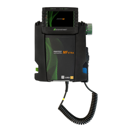
The Instrument Meanings of Symbols on the Instrument Warning concerning a point of danger Scope of Delivery (attention, observe documentation!) Standard scope of delivery for PROFITEST MF series: Protection category II device 1 Test instrument 1 Compact battery pack (Z502H) -
Page 8: Instrument Overview
12 Test plug holder * Can only be switched on with the key on the instrument 13 Fuses Accessories: 14 Holders for test probes (8) A PRO-HB (Z501V) test probe and measuring adapter holder – can be purchased separately Gossen Metrawatt GmbH... - Page 9 Two replacement fuses are also located under the battery com- only be switched on by pressing the key at the control panel. partment lid. ▼ This key has the same function as the key on the test plug. Gossen Metrawatt GmbH...
-
Page 10: Technical Data
Z502R charger Charging time Z502R charger: approx. 3 hours * * Maximum charging time with fully depleted batteries. A timer in the charger limits charging time to no more than 4 hours. Gossen Metrawatt GmbH... -
Page 11: Characteristic Values For Profitest Mf Tech
200 k … 999 k EXTRA 2.3 mA at 230 V 0.01 M 1.00 M … 9.99 M 1.00 M … 9.99 M ±(|10% rdg.|+2d) ±(|5% rdg.|+3d) 0.1 M 10.0 M … 30.0 M 10.0 M … 30.0 M Gossen Metrawatt GmbH... - Page 12 < 45 Hz ≥ U < 500 V 15 mA test current only applies if the RCD is set for I = 30 mA. Other- ΔN wise test current = ½ × I of the preselected RCDs. ΔN Gossen Metrawatt GmbH...
-
Page 13: Characteristic Values For Profitest Mf Xtra
EXTRA 2.3 mA at 230 V 1.00 M … 9.99 M 0.01 M 1.00 M … 9.99 M ±(|10% rdg.|+2d) ±(|5% rdg.|+3d) 10.0 M … 30.0 M 0.1 M 10.0 M … 30.0 M Gossen Metrawatt GmbH... - Page 14 < 45 Hz ≥ U < 500 V 15 mA test current only applies if the RCD is set for I = 30 mA. Other- ΔN wise test current = ½ × I of the preselected RCDs. ΔN Gossen Metrawatt GmbH...
- Page 15 < 10 or clamp meter current > 500 μA E.sel 100 and R 100 Where R Where d = 20 m Where d = 2 m Only where RANGE = 20 k Only where RANGE = 50 k or AUTO Gossen Metrawatt GmbH...
-
Page 16: Operating And Display Elements
Memory half full Connection Test – Mains Connection Test ( section 6.4) Attention! Connection OK L and N reversed The mains connection test may not be used to test sys- tems or system components for the absence of voltage! Gossen Metrawatt GmbH... -
Page 17: Led Indications, Mains Connections And Potential Differences
Phase conductor L and protective conductor PE reversed Is dis- All except for U played Neutral conductor interrupted (with probe only) Is dis- All except for U L and N are connected to the phase conductors. played Gossen Metrawatt GmbH... - Page 18 Conductor L2 missing Is displayed (3-phase measurement) Conductor L3 missing Is displayed (3-phase measurement) Conductor L1 to N Is displayed (3-phase measurement) Conductor L2 to N Is displayed (3-phase measurement) Conductor L3 to N Is displayed (3-phase measurement) Gossen Metrawatt GmbH...
- Page 19 Is dis- Battery charge level ≥ 50% played Is dis- L-PE Battery charge level ≥ 30% played N Is dis- Battery charge level ≥ 15% Setup, played EXTRA, Is dis- Battery charge level ≥ 0% played SENSOR Gossen Metrawatt GmbH...
- Page 20 Interference voltage / RLO Remedy: Device under test must be disconnected from all sources of RINS voltage Interference voltage > 20 V at the probes: PRO-RE RE (bat) H to E or S to E No measurement possible Gossen Metrawatt GmbH...
- Page 21 – Clamp is not connected or – Current through clamp is too small (partial earthing resistance too high) – Transformation ratio set incorrectly Remedy: Check clamp connection and transformation ratio. Check the batteries in the METRAFLEX P300 and replace if necessary. Gossen Metrawatt GmbH...
- Page 22 DC not possible with type A, F EXTRA RCM N ½ test current not possible with DC EXTRA RCM 2 × I / 5 × I with full-wave only N N N DC+ with 10 Ω only Gossen Metrawatt GmbH...
- Page 23 Test measurement: The test has not been passed. EXTRA I The leakage current measuring adapter is defective. Contact our repair service department. Test measurement: EXTRA I Check the fuse in the leakage current measuring adapter. Gossen Metrawatt GmbH...
- Page 24 The database in the instrument’s internal memory is empty after database transfer has been interrupted. Remedy: Reduce the size of the database in IZYTRONIQ or transfer the database without measured values (Transmit Structure key), if measured values already exist. Gossen Metrawatt GmbH...
-
Page 25: Operation
(Z502H/Z502O) or by inserting fully charged, commer- may result in overheating and thus deformation and ex- cially available rechargeable batteries or new batteries. See sec- plosion when charging them in the instrument. tion 7.1, “Power Supply”, on page 25. Gossen Metrawatt GmbH... -
Page 26: Instrument Settings
FACTORY SETTINGS Brightness menu (default settings) Display Illumination On-time Test Instrument On-Time Return to submenu 30 s 60 s 10 s 15 s 120 s 20 s 5 min No automatic shutdown, 30 s continuously on Gossen Metrawatt GmbH... - Page 27 Select time Apply settings Decrease hours Increase hours Decrease minutes Increase minutes Decrease seconds Increase seconds Set date Return to submenu Select date Apply settings Decrease day Increase day Decrease month Increase month Increase year Decrease year Gossen Metrawatt GmbH...
- Page 28 Measured values are invalid. The measurement results cannot be saved to memory. ➭ Press ESC in order to return to the main menu. Gossen Metrawatt GmbH...
- Page 29 The inspector cannot be changed. If an inspector’s name is incorrect, it can be deleted and a new inspector can be created with the correct name. Changes are not retroactive. Deleted inspectors are retained for tests which have already been performed. Gossen Metrawatt GmbH...
-
Page 30: Database
The test instrument and the PC must be connected with a USB cable in order to transfer structures and data. Distributor Note The rotary selector switch may not be set to the “U” posi- tion during data transmission. Gossen Metrawatt GmbH... - Page 31 Search for ID number or text. Continue searching. Edit menu Cursor LEFT: Select an alphanumeric character. Cursor RIGHT: Select an alphanumeric character. ENTER: accept an individual character. Acknowledge entry Scroll left Scroll right Delete character Gossen Metrawatt GmbH...
-
Page 32: Creating Structures (Example For Electrical Circuit)
Accept character ✓Save designation Delete character Character selection: A, a, 0, @ ✓ Enter a designation and then acknowledge it with Note ✓ and , because the entry Acknowledge your entry with will otherwise not be accepted. Gossen Metrawatt GmbH... -
Page 33: Searching For Structure Elements
If no further matches are found, the message shown above is dis- A check mark in the header means that the respective played. measurement has been passed. An X means that the measurement has not been passed. A circle means that the measurement has not been eval- uated. Gossen Metrawatt GmbH... -
Page 34: Use Of Barcode Scanners And Rfid Readers
Excel be read in as required for comments spreadsheet. Note The database is exited when the rotary selector switch is turned. Previously selected parameters in the database are not used for the measurement. Gossen Metrawatt GmbH... -
Page 35: General Information On Measurements
> 25 V or > 50 V, measurement is immediately inter- rupted. The U LED lights up red. If battery voltage falls below the permissible limit value the instru- ment cannot be switched on, or it is immediately switched off. Gossen Metrawatt GmbH... -
Page 36: Help Function
Product information is available here, including links to the individual device types. After accessing the website for your product type, you’ll find operating instruc- tions and other product documentation (e.g. the data sheet) in the “Download/Documentation” section. Gossen Metrawatt GmbH... -
Page 37: Setting Parameters Or Limit Values Using Rcd Measurement As An Example
6 The setting value is not permanently accepted for the respec- ✓ tive measurement until is pressed, after which the display is returned to the main menu. You can return to the main menu ✓ by pressing ESC instead of , without accepting the newly selected value. Gossen Metrawatt GmbH... -
Page 38: Freely Selectable Parameter Settings Or Limit Values
key. The new parameter is added to the list. Note Observe the predefined limits for the new setting value. Enter any places to the right of the decimal point as well. Gossen Metrawatt GmbH... -
Page 39: 2-Pole Measurement With Rapid Or Semiautomatic Polarity Reversal
N instrument or the test plug. L-PE L1-PE L1-N L1-PE N-PE L2-PE L2-N L2-PE L1-PE L3-PE L3-N L3-PE L2-PE L1-L2 N-PE L3-PE L2-L3 L1-N L+N-PE L1-L3 L2-N L1-N L3-N L2-N L1-L2 L3-N L2-L3 L1-L2 L1-L3 L2-L3 L1-L3 Gossen Metrawatt GmbH... -
Page 40: Measuring Voltage And Frequency
The selected connection type is dis- is prohibited by the standards, voltage polarity must be tested in played inversely (white on black). order to assure that all existing single-pole switches are installed to the phase conductors. Gossen Metrawatt GmbH... -
Page 41: Testing Rcds
30% residual current (if no bias current pole adapter. Suppression of RCD tripping by means of occurs within the system). bias magnetization with direct current is only possible via a country-specific plug insert, e.g. SCHUKO, or the 3- pole adapter. Gossen Metrawatt GmbH... -
Page 42: Current
Negative/positive half-wave Neg./pos. direct current x times tripping current: 1, 2, 5 (I max. 300 mA) N Connection: Without/with probe System type: TN/TT, IT Touch voltage: < 25 V, < 50 V, < 65 V Time to trip: Gossen Metrawatt GmbH... - Page 43 RCCB. However, the trip limit may be damaged. exceeded as a result of leakage current in the measuring circuit, e.g. due to interconnected consumers with EMC circuit, e.g. fre- quency converters or PCs. Gossen Metrawatt GmbH...
-
Page 44: Special Tests For Systems And Rcds
, must be applied to this end. If current rise is N linear, rising current may not exceed twice the value of I within a N period of 5 seconds. Testing with smoothed direct current must be possible in both test current directions. Gossen Metrawatt GmbH... -
Page 45: Testing Rccbs With 5 × I N
RCCB can be executed with this test in order to assure that the RCCB is not saturated by the pulsating direct current so that it no longer trips. Gossen Metrawatt GmbH... -
Page 46: Testing Of Special Rcds
Selective RCDs demonstrate delayed response charac- teristics. Tripping performance is briefly influenced (up to 30 s) due to pre-loading during measurement of touch voltage. In order to eliminate pre-charging caused by the measurement of touch voltage, a waiting period must be Gossen Metrawatt GmbH... -
Page 47: Srcd, Prcd-S (Schukomat, Sidos Or Comparable)
– as a rule an electrical tool – and the electrical outlet. Select Measuring Function N Set Parameter – SRCD / PRCD Type 1: Start Measurement Gossen Metrawatt GmbH... -
Page 48: 12.3.4 Type G Or R Rccb
180°. The longer of the two tripping times is decisive regard- ing the condition of the tested RCCB. Set Parameter – Start with Positive or Negative Half-Wave Waveform: 0°: Start with pos. half-wave 180°: Start with neg. half-wave Negative direct current Positive direct current Gossen Metrawatt GmbH... -
Page 49: Testing Residual Current Circuit Breakers In Tn-S Systems
As a rule, the display for touch voltage is also 0.1 V, because the nominal residual current of 30 mA together with minimal loop Start Measurement resistance result in a very small voltage value: = 1 × 30 mA = 30 mV = 0.03 V × I N IN Gossen Metrawatt GmbH... -
Page 50: Testing Of 6 Ma Residual Current Devices Rdc-Dd/Rcmb
The RCMB is tested with nominal residual currents of 6 to 300 mA. Start Measurement Time to trip: 6 mA 10.0 s 60 mA 0.3 s 200 mA 0.1 s Note The RDC-DD is tested with nominal residual currents of 6 to 200 mA. Start Measurement Gossen Metrawatt GmbH... -
Page 51: Testing Of Breaking Requirements For Overcurrent Protective Devices, Measurement Of Loop Impedance And Determination Of Short-Circuit Current (Zl-Pe And Isc Functions)
Only AC measurements can be performed with the 2- pole adapter. Suppression of RCD tripping by means of bias magnetization with direct current is only possible via a country-specific plug insert, e.g. SCHUKO, or the 3- pole adapter (neutral conductor N required). Gossen Metrawatt GmbH... -
Page 52: Measurement With Positive Half-Waves (Profitest Mf Tech Only)
(fuse or circuit breaker) for a line voltage of 230 V after allowance has been made for maximum measuring error can be determined with the help of Table 6 on page 97 based on mea- sured short-circuit current (corresponds to IEC 60364-6). Gossen Metrawatt GmbH... -
Page 53: Settings For Calculating Short-Circuit Current - Parameter Isc
10% max. Frequency of the applied voltage, “f ” is displayed if frequency f max. deviates from nominal frequency by 1% Tripping current (see data sheet for circuit breakers / fuses) % Test instrument intrinsic error Gossen Metrawatt GmbH... -
Page 54: Measuring Supply Impedance (Z L-N Function)
10% max. Frequency of the applied voltage, “f ” is displayed if frequency f deviates from nominal max. frequency by 1% Tripping current (see data sheet for circuit breakers / fuses) % Test instrument intrinsic error Gossen Metrawatt GmbH... - Page 55 HELP key. The table shows maximum permissible nominal current depen- dent on fuse type and breaking requirements. Key: I = breaking current, I = short-circuit current, I = nominal current, t = time to trip Gossen Metrawatt GmbH...
-
Page 56: Earthing Resistance Measurement (Function R E )
(at nominal conditions of use), can be determined with the help of Table 2 on page 96. Intermediate val- ues can be interpolated. Gossen Metrawatt GmbH... -
Page 57: Earthing Resistance Measurement - Mains Powered
See section 15.4 through section 15.6 regarding advisable types. parameters for the respective measurement and connection Performing Measurements types. See section 15.7 through section 15.11. Performing Measurements See section 15.4 through section 15.6. Gossen Metrawatt GmbH... -
Page 58: Earthing Resistance, Mains Powered - 2-Pole Measurement With 2-Pole Adapter Or Country-Specific Plug (Schuko) Without Probe
The calculated earthing resistance thus includes operational earth conductor resistance as a safety factor. If the parameter is selected, steps 1 through 3 are executed automatically by the test instrument. Select Measuring Function Select Operating Mode Gossen Metrawatt GmbH... -
Page 59: Mains Powered - 3-Pole Measurement: 2-Pole Adapter With Probe
Select Measuring Function Limit Value > Limit Value Select Operating Mode R Connection Start Measurement To be connected: 2-pole adapter and probe Note The following diagram appears if the 2- pole adapter is connected incorrectly. Gossen Metrawatt GmbH... -
Page 60: Earthing Resistance Measurement, Mains Powered - Measuring Earth Electrode Potential (U Function)
The calculated value is displayed at the display panel. Select Measuring Function R Select Operating Mode Select Measuring Range Start Measurement Connection Note The following diagram appears if the 2- pole adapter is connected incorrectly. To be connected: 2-pole adapter and probe Gossen Metrawatt GmbH... -
Page 61: Earthing Resistance Measurement, Mains Powered - Selective Earthing Resistance Measurement With Current Clamp Sensor As Accessory
In order to prevent electric shock, keep the surface of the METRAFLEX clean and free of contamination. • Before use, make sure that the flexible current sensor, the con- nector cable and the electronics housing are dry. Gossen Metrawatt GmbH... - Page 62 Selective earthing resistance measured via clamp Clamp Total earthing resistance measured via probe, Probe comparative value Note The following diagram appears if the 2- pole adapter is connected incorrectly. Gossen Metrawatt GmbH...
-
Page 63: Earthing Resistance Measurement, Battery Powered, "Battery Mode" - 3-Pole (Profitest Mf Xtra Only)
The measurement cables must be well insulated in order to prevent shunting. In order to keep the influence of pos- sible coupling to a minimum, the measurement cables should not cross each other or run parallel to each other over any considerable distance. Gossen Metrawatt GmbH... -
Page 64: Earthing Resistance Measurement, Battery Powered, "Battery Mode" - 4-Pole (Profitest Mf Xtra Only)
Gossen Metrawatt GmbH... - Page 65 “Earthing Resistance Mea- surement for a Large Scope Earthing System” on page 65. (Curve I). If a line parallel to the abscissa is drawn through inflection point S1, this line divides the resistance curve into two parts. Gossen Metrawatt GmbH...
-
Page 66: (Profitest Mf Xtra Only)
➭ Connect the Z3512A current clamp sensor to jacks (15) and (16) at the test instrument. ➭ Attach the current clamp sensor to the earth electrode. Select Measuring Function Select Operating Mode The selected operating mode is displayed inversely: white battery icon against black background. Gossen Metrawatt GmbH... -
Page 67: (Profitest Mf Xtra Only)
➭ Connect the Z3512A current clamp sensor to jacks 15 and 16 at the test instrument. ➭ Attach the 2 clamps to an earth electrode (earth spike) at dif- ferent heights with a clearance of at least 30 cm. Gossen Metrawatt GmbH... -
Page 68: E (Profitest Mf Xtra Only)
➭ Connect the probes, the auxiliary electrode and the electrode of Precipitation (earth electrode depth < 1.5 m) via the 4 mm banana plug sockets at the PRO-RE adapter. In doing so, observe labeling on the banana plug sockets. Gossen Metrawatt GmbH... - Page 69 = Edge length (m) of a square ground plate; a is replaced with the fol- lowing for rectangular plates: b x c, where b and c are the two sides of the rectangle. J = volume (cubic meters) of an individual foundation footing Gossen Metrawatt GmbH...
-
Page 70: Measurement Of Insulation Resistance
Insulation measurement with rising test voltage is ended: where x, y = 1, 2, 3 • As soon as specified maximum test voltage U is reached and the measured value is stable * AUTO parameter (see section 10.9) Gossen Metrawatt GmbH... - Page 71 The test instrument uses continuously rising test voltage for this measuring function, up to the maximum selected voltage limit. The measuring procedure is started by pressing the ON/START ▼ key and runs automatically until one of the following events Gossen Metrawatt GmbH...
-
Page 72: Special Case: Earth Leakage Resistance (Reiso )
This measurement is performed in order to determine electro- liable ground connection). static discharge capacity for floor coverings in accordance with EN 1081. Start Select Measuring Function Measurement The limit value for earth leakage resistance from the relevant regu- lations applies. Gossen Metrawatt GmbH... -
Page 73: Measuring Low-Value Resistance Of Up To 200 (Protective Conductor And Equipotential Bonding Conductor)
UL/RL LED lights up. Limit values can be selected within a range of 0.10 to 10.0 (editable). The limit value is displayed above the measured value. Gossen Metrawatt GmbH... -
Page 74: Measurement With Constant Test Current
The instrument’s batteries are exposed to excessive stress during insulation resistance measurement. For measurement with cur- rent flow in one direction, only press and hold the ON/START ▼ key as long as necessary for the measurement. Gossen Metrawatt GmbH... -
Page 75: Protective Conductor Resistance Measurement
(see figure at the right). In this case as well, the test instrument started until the symbol at the right appears. automatically takes subsequently required waiting time into account before you can reactivate the PRCD and start the mea- surement over again. Gossen Metrawatt GmbH... -
Page 76: Measurement With Accessory Sensors
Clamp Use only current clamp sensors which are specifically of- Output Range fered as accessories by Gossen Metrawatt GmbH. Other current clamp sensors might not be terminated with an output load at the secondary side. Dangerously high voltage may endanger the user and the device in such cases. -
Page 77: Special Functions - Extra Switch Position
Testing of electric section vehicle operating 19.9 on ✓ ✓ statuses at charging page 87 stations per IEC 61851-1 Documentation of section fault simulations at 19.10 on ✓ — PRCDs with the PRO- page 88 FITEST PRCD adapter Gossen Metrawatt GmbH... -
Page 78: Voltage Drop Measurement
Limit value per DIN VDE 0100-520: U < 4% between the distribution network and the consuming device (adjustable up to 10% in this case) Limit value per NIV: U < 5% Gossen Metrawatt GmbH... -
Page 79: Measuring The Impedance Of Insulating Floors And Walls (Standing Surface Insulation Impedance)
Do not touch the metal plate or the damp cloth with your bare hands. No more than 50% line voltage may be applied to these parts! Current with a value of up to 3.5 mA may flow! The measured value would be distorted as well. Gossen Metrawatt GmbH... -
Page 80: Testing Meter Startup With Earthing Contact Plug - Kwh Function
In the event that “NOT OK” is selected, an error is indicated by the UL/RL LED which lights up red. The measured value cannot be saved to memory and included in the test report until it has been evaluated. Save measured value Gossen Metrawatt GmbH... -
Page 81: Leakage Current Measurement With Pro-Ab Leakage Current Adapter As Accessory
(in the case of overranging) be manually cor- rected at the measuring adapter and the test instrument. Individual limit values can be adjusted after pressing the Limits function key. Exceeded limit values are indicated by the red limit value LED at the test instrument. Gossen Metrawatt GmbH... -
Page 82: Testing Insulation Monitoring Devices - Imd Function (Profitest Mf Xtra Only)
➭ If evaluation is NOT OK: the UL/RL LED lights up red. Resistance R START ➭ Save: by pressing the soft key. Numerous parameters are available for setting resistance R START with which measurement is begun. Measurement can be aborted by pressing the ON/START ▼ or ESC key. Gossen Metrawatt GmbH... - Page 83 (see also section 9.4). With the help of the key shown at the right (MW: measured value / PA: parameter), the setting parameters can be displayed for this measurement. Gossen Metrawatt GmbH...
-
Page 84: (Profitest Mf Xtra Only)
1 second! pressing the ESC key. Connection Limit Values Set Limit Values U Limit Value U % > Limit Value R Gossen Metrawatt GmbH... -
Page 85: (Profitest Mf Xtra Only)
10 … 500 mA Type 1: RCD, SRCD, PRCD … Type 2: AC , A/ Nominal current: 6 … 125 A * Type B = AC/DC sensitive Touch voltage: < 25 V, < 50 V, < 65 V Gossen Metrawatt GmbH... -
Page 86: Testing Residual Current Monitors - Rcm Function (Profitest Mf Xtra Only)
In the event that NOT OK is selected, an error is indicated by the UL/ RL LED which lights up red. The measured value cannot be saved to memory and included in the test report until it has been evaluated. Touch voltage: < 25 V, < 50 V, < 65 V Gossen Metrawatt GmbH... -
Page 87: Checking The Operating Statuses Of Electric Vehicles At Charging Stations Per Iec 61851 (Profitest Mf Xtra)
A/E (01 = A, 02 = B, 03 = C, 04 = D, 05 = E). Status variants can be skipped by pressing the I key at the test N instrument or the test plug. Gossen Metrawatt GmbH... -
Page 88: Prcd - Test Sequences For Documenting Fault Simulations At Prcds With The Profitest Prcd Adapter (Profitest Mf Xtra Only)
— AUTO AUTO Semi-automatic change of fault simulations The test steps are displayed at the test instrument. Their mean- ings and the associated switch positions at the PROFITEST PRCD are listed in the above table. Gossen Metrawatt GmbH... - Page 89 Simulation of PE to Phase (step 8) PRCD-S, 3-phase: 18 test steps Contact ON Key at PRCD with Probe (step 10) Measurement of Protective Conductor Current with a Current Clamp Transformer (step 11) PRCD-K, single-phase: 5 test steps Gossen Metrawatt GmbH...
- Page 90 Test steps can be skipped during fault simulation by pressing the key at the test instrument or the test plug. N Simulation of PE to Phase (step 17) Measurement of Protective Conductor Current with a Current Clamp Transformer (step 18) Gossen Metrawatt GmbH...
-
Page 91: Test Sequences (Automatic Test Sequences) - Auto Function
As a result, the newly created test sequence step must be entered here. should be checked at the test instrument before it’s per- ➭ Save your settings by clicking the manently added to the database. icon. Gossen Metrawatt GmbH... -
Page 92: Reset (Default Settings)
An active sequence can be aborted by pressing the ESC key and then acknowledging. Sequence Ended appears after the last test step is completed. The initial menu, List of Test Sequences, is once again displayed after acknowledging the prompt. Gossen Metrawatt GmbH... -
Page 93: Maintenance
Only original fuses from Gossen Metrawatt GmbH may be used (order no. 3-578-285-01 / SIBA 7012540.3.15 Query Current Status SI-EINSATZ FF 3.15/500 6.3X32). -
Page 94: Contact, Support And Service
Contact, Support and Service Important Information Concerning Licenses Gossen Metrawatt GmbH can be reached directly and simply – This test instrument is subject to license terms and conditions. we have a single number for everything! Whether you require sup- In addition to the software developed by Gossen Metrawatt... -
Page 95: Disposal And Environmental Protection
Old devices, electrical or electronic accessories and waste batter- ies (including rechargeable batteries) used in Germany can be returned free of charge to Gossen Metrawatt GmbH or the service provider responsible for their disposal in compliance with applica- ble regulations, in particular laws concerning packaging and haz- ardous goods. -
Page 96: Appendix
2.38 3.00 2.82 3.00 2.86 3.50 3.30 3.50 3.34 4.00 3.78 4.00 3.82 4.50 4.25 4.50 4.30 5.00 4.73 5.00 4.78 6.00 5.68 6.00 5.75 7.00 6.63 7.00 6.71 8.00 7.59 8.00 7.67 9.00 8.54 9.00 8.63 Gossen Metrawatt GmbH... - Page 97 2.34 k 1.12 k 2240 3.18 k Example Display value of 90.4 A next lower value for circuit breaker characteristic B from table: 85 A nominal current (I ) of the pro- tective device: max. 16 A Gossen Metrawatt GmbH...
-
Page 98: At Which Values Should/Must An Rcd Actually Be Tripped? Requirements For Residual Current Devices (Rcd)
N Phase angle of 135° el 0.11 … 1.4 I N Pulsating direct current superimposed with 6 mA smooth, Max. 1.4 I + 6 mA N direct residual current Smooth direct current 0.5 … 2 I N Gossen Metrawatt GmbH... -
Page 99: Testing Electrical Machines Per Din En 60204 - Applications, Limit Values
Measurement of loop impedance, as well as (with PROFITEST PRIME AC only) other measurements required for the testing of electrical machines, can be performed with test instruments from the Limit Values per DIN EN 60204-1 PROFITEST MF series. Measurement Parameters Cross- Standard... -
Page 100: Periodic Testing Per Dguv V 3 (Previously Bgv A3) - Limit Values For Electrical Systems And Operating Equipment
Protective conductor current Maximum Permissible Limit Values for Equivalent Leakage Current in mA Test Standard PC I: 3.5 EN 50678 / 1 mA/kW DIN EN 50699 PC II: 0.5 For devices with heating power 3.5 kW Gossen Metrawatt GmbH... - Page 101 Gossen Metrawatt GmbH Prepared in Germany • Subject to change, errors excepted • PDF version available on the Internet All trademarks, registered trademarks, logos, product names and company names are the property of their respective owners. Phone: +49 911 8602-111...
Need help?
Do you have a question about the PROFITEST MF Series and is the answer not in the manual?
Questions and answers