
Subscribe to Our Youtube Channel
Related Manuals for Gossen MetraWatt R6000


Summary of Contents for Gossen MetraWatt R6000
- Page 1 Installation Instructions R6000 3-349-163-29 8-Channel Controller 8/3.14 Alternative...
-
Page 2: Table Of Contents
Contents Page Safety Precautions ......... 3 1.1 Meanings of symbols on the instrument . -
Page 3: Safety Precautions
Safety Precautions The R6000 controller is manufactured and tested in accordance with safety regulations IEC 61010-1 / EN 61010-1 / VDE 0411 part 1. If used for its intended purpose, safety of the user and of the device is assured. -
Page 4: Identification By Means Of Serial Plate
Figure 1 Serial Plate Labeling Identification According to Article Number and Device Feature Code Article Number / Feature Description R6000 8-Channel Controller Inputs / Outputs 16 binary inputs / outputs 20 binary inputs / outputs 16 binary inputs / outputs, 4 continuous outputs... -
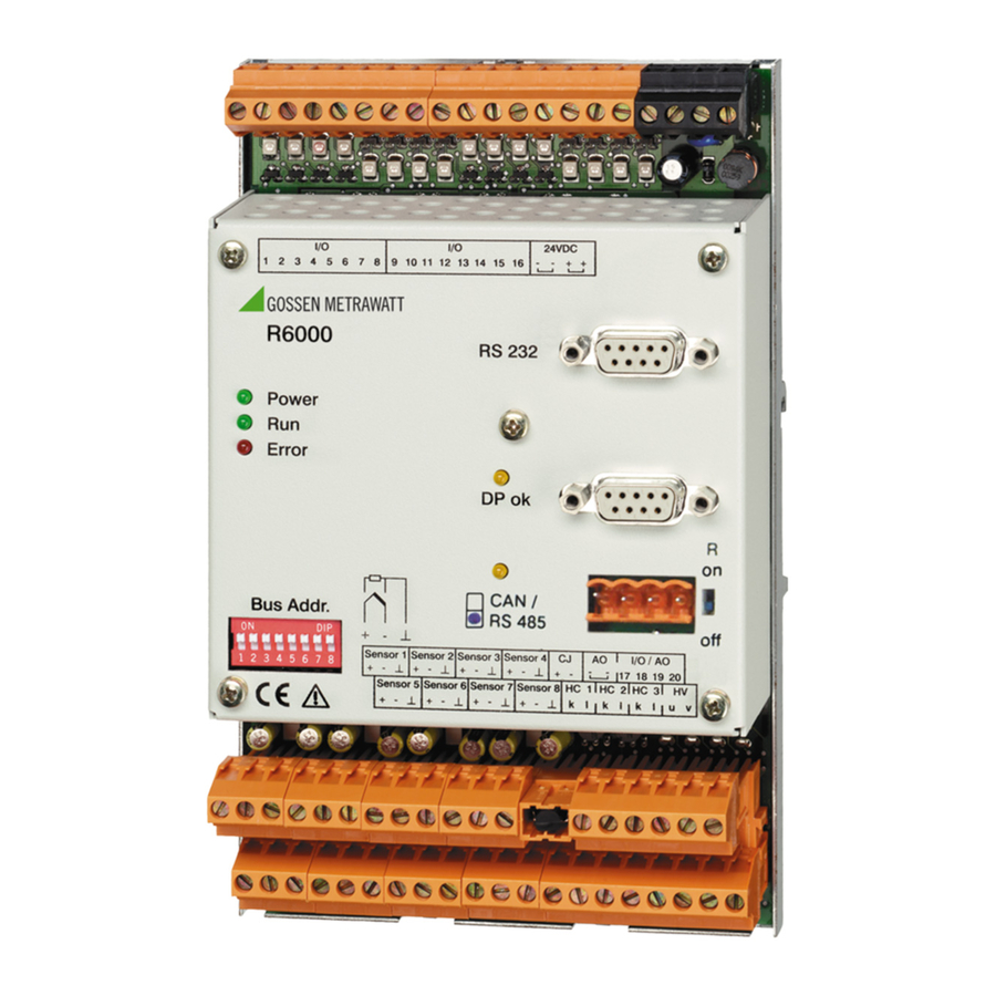
Page 5: Identification Of Features At The Housing Front Panel
Device Variant According to Included Features Mounting, Setup and Installation Instructions The R6000 is a compact 8-channel temperature controller in a top-hat rail mount housing. The controller is mounted by snapping it onto a top-hat rail in accordance with DIN EN 50022. -
Page 6: Dimensional Drawing
Unobstructed air circulation must always be assured when one or sev- eral devices are installed. The ambient temperature underneath the devices may not exceed 50° C. Aggressive vapors shorten the service life of the controller. Dimensional Drawing All dimensions in millimeters Figure 4 Dimensional Drawing for Top-Hat Rail Mounting GMC-I Messtechnik GmbH... -
Page 7: Electrical Connection
Only terminal blocks of like polarity or identical color may be plugged onto the appropriate bases. Mismatching of the terminal blocks may result in damage to the R6000 controller or interconnected components. GMC-I Messtechnik GmbH... -
Page 8: Terminal Assignments
Terminal Assignments Auxiliary voltage Binary inputs / outputs (I / O) Service interface Profibus-DP (Version F2) Connection CAN / RS-485 (Version F1/F3/F4/F7/F8) Bus connection resistance on / off Reference junction connection Optional additional outputs Version A0 not assigned Version A1 Sensor Heating circuit monitoring Binary inputs/outputs (I/O) -
Page 9: Auxiliary Voltage
In this way, supply power can be looped through to several R6000 controllers. The terminals have a maximum current carrying capacity of 10 A (also in the event of malfunction) which may not be exceeded! The terminal block for auxiliary voltage is black. -
Page 10: Thermocouple And Pt100 Measurement Inputs, 20 Ma
Attention! After overload protection has been triggered, not only does the overload have to be eliminated, all other outputs must be de-energized as well in order to allow for self-restoration of the circuit breaker. Self-restoration may take several minutes. If the I/Os are used as inputs, control is accomplished either by means of an active positive signal at the auxiliary voltage negative pole, or with a floating contact which switches the auxiliary voltage positive pole to the input. -
Page 11: Remote Cold Junction (Cj)
2-pole terminal block. The plug-on reference junction (CJ) at the R6000 is removed and is replaced with the 2-pole terminal block. The temperature sensor is attached at the transition from the thermocouple or the equalizing lead... -
Page 12: Additional Binary Inputs / Outputs (I/O)
2-pole terminal block at the R6000. The original reference junction which has now been removed from the R6000 is not used. Additional Binary Inputs / Outputs (I/O) Device variants including feature A1 have four additional I/Os. -
Page 13: Heating Current Monitoring (Hc 1
Heating Current Monitoring (HC 1 ... 3, HV) R6000 HC1 HC2 HC3 HV Figure 10 Schematic Diagram, Current Transformer Connection Commercially available current transformers with max. 1 A secondary current are connected to terminals HC k and l. Compliance voltage is max. -
Page 14: Data Interfaces
Data Interfaces Type Service Fieldbus Interface Interface Feature F3/F4/F7/F8 Interface RS 232 Profibus DP CAN / RS 485 CANOpen Maximum number of devices Range of addresses – 0 ... 126 0 ... 127 0 ... 254 Transmission speed 9.6 or 19.2 9.6 kBaud ... - Page 15 – The two bus ends should be terminated with characteristic wave impedance. This is accomplished by setting the “R” switch at the R6000 to “on”. CAN (variant with feature F1) 4-pole terminal block Figure 12 Diagram of Terminal Block for CAN Interface...
- Page 16 Profibus DP (variant with feature F2) 9-pin sub-miniature plug connector at the controller 5 4 3 2 1 9 8 7 6 Figure 13 Diagram of Sub-miniature Plug for Profibus DP Interface Pin Assignments for Sub-miniature Plug Connector for Profibus DP Interface Pin Number Designation Assignment / Description...
-
Page 17: Led Functions
Note! Designations A and B are not defined uniformly in various stan- dards or for various devices. If the bus does not function, A and B may be reversed. LED Functions LEDs provide information regarding the status of the device, as well as the switching outputs and switching inputs of the controller and the fieldbus. -
Page 18: Device Performance After Connecting Auxiliary Voltage
No connection between negative pole at the actuators and auxiliary voltage Profibus LED does not light up. No data exchange RS 485 / CAN LED does not light up. No transmission from R6000 e.g. due to incorrect address, bus terminator switch set incorrectly GMC-I Messtechnik GmbH... -
Page 19: Parameters Configuration And Operation
The operating instructions should be made available to all users. Maintenance and Service The R6000 controller does not require maintenance at regular inter- vals. If the controller should nevertheless require replacement, it can be removed from the rail by pulling on the tab at the bottom of the device. -
Page 20: Characteristic Values
Characteristic Values Inputs / Outputs Sampling rates 100 ms for each controlled variable Thermocouple Measurement Input Thermocouples per IEC 60584 / EN 60584 / DIN 43710 Measuring range 0 ... 50 mV 0,3 mV Accuracy / Error Resolution 0.1 K Continous overload AC sinusoidal 50 / 60 Hz / 50 V AC 1 V DC... - Page 21 Heating Voltage Input Measuring range 10 ... 50 V AC (direct connection of a commercially available measuring transducer) Resolution < 0.1 % of upper range value Accuracy < 5 % of upper range value Binary Inputs / Outputs Output function active switching outputs supplied directly from auxiliary voltage Function...
- Page 22 Data Interfaces Service Interface RS 232 Max. number of devices Range of addresses – Transmission speed 9.6 / 19.2 kBaud Protocol per EN 60870 Connection 9-pin sub-miniature plug Field Bus Interfaces Profibus-DP Max. number of devices Range of addresses 0 ... 126 Transmission speed 9.6 kBaud ...
- Page 23 Electromagnetic Compatibility Interference emission IEC 61326-1 / EN 61326-1 class A Interference immunity IEC 61326 / A1 / EN 61326 / A1 criterion A, B Ambient Conditions Annual mean relative humidity, no condensation 75 % Ambient temperature – Nominal range of use 0 °C ...
-
Page 24: Repair And Replacement Parts Service, And Rental Instrument Service
Repair and Replacement Parts Service, and Rental Instrument Service When you need service, please contact: GMC-I Service GmbH Service Center Thomas-Mann-Str. 20 90471 Nürnberg • Germany Phone +49 911 817718-0 +49 911 817718-253 E-Mail service@gossenmetrawatt.com www.gmci-service.com This address is only valid in Germany. Please contact our representatives or subsidiaries for service in other countries.
Need help?
Do you have a question about the R6000 and is the answer not in the manual?
Questions and answers