
Subscribe to Our Youtube Channel
Related Manuals for Gossen MetraWatt R2080


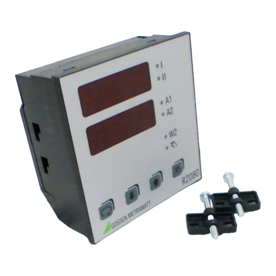
Summary of Contents for Gossen MetraWatt R2080
- Page 1 Operating Instructions R2080, R2100, R2180 3-349-219-15 Compact Controller 96 x 96 mm 2/9.02...
-
Page 2: Table Of Contents
GTR0208/GTR0210/GTR0218 ....9 Connection R2080 ......10 Warning concerning a source of danger Connection R2100 . -
Page 3: Safety Features And Precautions
Avoid the use of solvents, cleansers and abrasives. Repair and Parts Replacement Repairs and the replacement of parts conducted at a live open instrument may only be carried out by trained personnel who are familiar with the dangers involved. GOSSEN METRAWATT GMBH... -
Page 4: Repair And Replacement Parts Service
Repair and Replacement Parts Service When you need service, please contact: GOSSEN METRAWATT GMBH Service-Center Thomas-Mann-Straße 20 D-90471 Nürnberg Telefon +49-(0)-911-86 02-410/256 Telefax +49-(0)-911-86 02-253 E-Mail service@gmc-instruments.com This address is only valid in Germany. Please contact our representatives or subsidiaries for service in other countries. -
Page 5: Identification Of Controller R2080
Identification of Controller R2080 Features A3, A13, C23 and E3 of controller GTR0208 Feature Designation cannot be replaced. Electronic PDPI controller R2080 Feature B2 is not compatible with GTR0208. Controller types Auxiliary voltage is generally AC 110 … 230 V. -
Page 6: Identification Of Controller R2100
0 … 5 mA Direct current 0 … 20 mA 0 … 20 mA, display 0.00 … 2.00 Output type 1 switching point Relay Transistor Limit contact none MIN / MAX Rupture protection direct action reverse action GOSSEN METRAWATT GMBH... -
Page 7: Identication Of Controller R2180
A switch to deactivate the control outputs is always 32 … 2192 °F available (see feature F1 of controller GTR0218). 0 … 1600 °C type R Pt13Rh-Pt 32 … 2912 °F 0 … 1600 °C type S Pt10Rh-Pt 32 … 2912 °F GOSSEN METRAWATT GMBH... -
Page 8: Mechanical Installation / Preparation
R2080, R2180 and R2100 G0 Push the screw clamps first all the way up to the limit stop in direction 1 and subse- quently in direction 2 for this purpose. -
Page 9: Differences Between R2080/R2100/R2180 And Gtr0208/Gtr0210/Gtr0218
CnF1 = 0xx0 to 0xx4 while using the break contact (reverse action principle). Switching point distance ∆w can only be set as a relative MAX alarm to a value above zero for the R2080 / R2180. Heating current display / monitoring Heating current transformer GTY 2570 127 R0x can no longer be used in connection with R2080. -
Page 10: Connection R2080
Connection R2080 Binary Auxiliary Input Voltage Transistor Output for Controlling SSRs 110 - 230 V∼ A01, A11, – – + II A02, A04, A12, A14, Heating Current Switching Output Transf. Sensor GOSSEN METRAWATT GMBH... -
Page 11: Connection R2100
Connection R2100 Binary Auxiliary Input Voltage Transistor Output for Controlling SSRs 110 - 230 V∼ – – + II Heating Current Switching Output Transf. C01 ... C24 10 V C30, C31 20 mA Sensor Alarms GOSSEN METRAWATT GMBH... -
Page 12: Connection R2180
Connection R2180 Binary Auxiliary input Voltage Transistor Output for Controlling SSRs 110 - 230 V∼ – – + II A2, A3, Heating Current Switching Output Transf. Sensor GOSSEN METRAWATT GMBH... -
Page 13: Electrical Connection
Performance After Activating Auxiliary Voltage LED Segment Test Software Version approx. 2 s approx. 1.5 s Current Configuration CnF1 Hardware Designation Actual Value approx. 1.5 s Current G Designation Setpoint or oFF Configuration CnF2 GOSSEN METRAWATT GMBH... -
Page 14: Display - Setpoint Selection - Operation
Switchover Off ↔ automatic operation selection (and parameter setting) The value is changed directly. After 2,5 s or after pressing key , the value is stored to memory and becomes active. This is acknowledged by a brief blackout of the display. GOSSEN METRAWATT GMBH... -
Page 15: Operating Flowchart
– no alarm function – By pressing key Act. val. switching output I („heating“) / – no error signalling II („cooling“) is directly controlled. – The actuating outputs are inactive unless keys are pressed. GOSSEN METRAWATT GMBH... -
Page 16: Parameters Configuration
SP L ... X2 Maximum setpoint X1 ... SP H Minimum setpoint Maximum PWR –100 ... 100 % Actual value correction Only with designations (Auto), –MBU/4 ... +MBU / 4 0 (see Balancing) C01 ... C24 GOSSEN METRAWATT GMBH... -
Page 17: Limit Value Monitoring
Suppression is active when auxiliary power is activated, if the current setpoint is changed or setpoint 2 is activated, or if switching takes place from off to automatic operation. GOSSEN METRAWATT GMBH... -
Page 18: Adjusting Control Performance - Manual Self-Tuning
Set dbnd to 0 in order to cause further overshooting with active switching output II. Record two overshoots – and two undershoots. Record on-time T and off-time T at switching output I or the continuous output for the last oscillation. GOSSEN METRAWATT GMBH... - Page 19 However, calculated values for tu may be very inaccurate in this case under certain cir- cumstances. – Same preparation as for actuation test. The test can be performed without a recorder if the actual value is observed at the display, and if times are measured with a stopwatch. GOSSEN METRAWATT GMBH...
- Page 20 Adjust the setpoint to the required value. The dead band can be increased from dbnd = 0 for 3-step and step-action controllers if control of switching – output I and II changes too rapidly, for example due to an unsteady actual value. GOSSEN METRAWATT GMBH...
-
Page 21: Self-Tuning
/ off with the key. – If an error occurs during self-tuning, the controller no longer reads out an actuating signal. Self-tuning must be aborted in this case. Additional information regarding error messages upon request. GOSSEN METRAWATT GMBH... -
Page 22: Alarms
SE L and CE) while other error messages appear in the upper display. 3. The display is switched to the operating level 30 seconds after value selection has been completed during configuration or parameter setting. 4. Exceptions and additional information are included in the following table: GOSSEN METRAWATT GMBH... - Page 23 Close the control loop: Check the sensor, the actuators and the heater for correct functioning. Check sensor-heater assignments (wiring). Correctly optimize control parameters tu and Pb 1. Restore default configuration and default parameters, and then reconfigure, or load user-defined default settings. GOSSEN METRAWATT GMBH...
-
Page 24: Setpoint Ramps
The default setting for the GTZ 4121 is 42.7 A. If the GTZ 4121 current transformer is not used for acquiring heating current, the current value must be selected at which the utilized transformer generates an output voltage of 10 V DC. GOSSEN METRAWATT GMBH... -
Page 25: Configuration
2-step controller, cooling absolute inactive 3-step controller relative inactive 3-step controller, water cooling absolute NC contact Step-action controller relative active absolute relative inactive absolute NO contact relative active absolute active relative inactive absolute NC contact relative active absolute GOSSEN METRAWATT GMBH... - Page 26 0 ... 10 V designation C30, signal °C 4 ... 20 mA °F (no function) Saving and loading of device settings see page 28 Switching to and from °C / °F not effective for R2100 C30 and C31 GOSSEN METRAWATT GMBH...
- Page 27 Setpoint 2 relative inactive absolute contact relative active absolute relative inactive absolute contact relative Manual / active absolute automatic or PWR out off- relative inactive absolute contact relative active absolute GOSSEN METRAWATT GMBH...
-
Page 28: Saving And Loading Device Settings
A harmonic-free PDPI control algorithm regulates switching output I or II in order to increase or decrease the actual value. The duration of the actuating impulse is equal to tc. The dead Step-action controller band dbnd is symmetric to the setpoint. GOSSEN METRAWATT GMBH... -
Page 29: Manual Operation With Binary Input
If a machine requires an average of 70% heating power during production operation, but only 10% during idle time, the difference of Y ST is set to 60%, and the binary input is only activated during production. GOSSEN METRAWATT GMBH... -
Page 30: Heating Current Monitoring
– Monitoring is not active: where controller sort = limit transducer, actuator or step-action controller during self-tuning with standard signal input (R2100 C30, C31) where PWR limiting Y H < 20% GOSSEN METRAWATT GMBH... -
Page 31: Technical Data
Operating voltage 300 V per DIN EN 61010 EMC requirements IEC/EN 61326 For complete technical data refer to the following data sheets: Controller R2080: Order no. 3-349-216-03 Controller R2100: Order no. 3-349-217-03 Controller R2180: Order no. 3-349-218-03 GOSSEN METRAWATT GMBH... - Page 32 Printed in Germany • Subject to change without notice GOSSEN METRAWATT GMBH Thomas-Mann-Str. 16-20 Phone +49-(0)-911-8602-0 90471 Nürnberg • Germany +49-(0)-911-8602-669 E-Mail info@gmc-instruments.com www.gmc-instruments.com...
Need help?
Do you have a question about the R2080 and is the answer not in the manual?
Questions and answers