Table of Contents
Advertisement
Advertisement
Table of Contents

Related Manuals for Gossen MetraWatt R2600


Summary of Contents for Gossen MetraWatt R2600
- Page 1 Operating Instructions R2600 / R2601 3-348-778-15 Electronic Controller 6/3.01...
-
Page 3: Table Of Contents
CONTENTS Page CONTENTS Page Safety features and safety precautions ..........4 Calibration ..................30 Maintenance ................... 5 Self-optimizing ................31 Repair and replacement parts service ..........5 Manual optimizing ................. 32 Identifying the unit ................6 Set point ramps ................36 Physical installation / Getting started .......... -
Page 4: Safety Features And Safety Precautions
Safety features and safety precautions The R2600 / R2601 controller is constructed and tested in compliance with the safety rules of IEC 1010-1 / VDE 0411-1. When properly used, the safety of both the user and the unit is assured. -
Page 5: Maintenance
Maintenance Case Special maintenance of the case is not required. Take care that the surface is clean. Use a slightly moist cloth for cleaning. Do not use solvents, detergents and scouring agents. Repair and replacement of parts Repair or replacement of parts with the tester open and alive must only be performed by a skilled person which is familiar with the danger involved. Repair and replacement parts service When you need service, please contact: GOSSEN-METRAWATT GMBH... -
Page 6: Identifying The Unit
Electronic controller with self-optimizing facility, second set point, 2 limit relays, front dimensions 48 x 96 mm (W x H) R2600 Electronic controller with self-optimizing facility, second set point, 2 limit relays, front dimensions 96 x 48 mm (W x H) - Page 7 Connection plug Connection from the side Connection from the rear Data interface None RS 485 / RS 232 internal switch-over possible Configuration Default setting Setting as per customer's request Operating German / English instructions French / Italian None 110V 230V 110V 230V Data interface...
-
Page 8: Physical Installation / Getting Started
GOSSEN-METRAWATT GMBH Physical installation / Getting started The R2600 / R2601 is meant for panel installation. As far as possible, the mounting site should be free from vibrations. Aggressive vapors reduce the service life of the controller. Observe the VDE 0100 specifications when performing any work. Work on the controller must only be performed by a qualified person who is familiar with the danger involved. - Page 9 Locking the two screw clamps (R2600 upper and lower side of case, R2601 right and left side of case): – Slide in direction 1 up to the stop – Slide in direction 2 up to the stop Location of the 5-pin DIP switch...
-
Page 10: Electrical Connection
GOSSEN-METRAWATT GMBH Electrical connection Binary Binary Transistorized output Contin. output RS 232 / Auxiliary voltage input 1 input 2 20 mA / 10 V RS 485 SP 2 A2, A3, A4 AC 230 V AC 110 V AC 24 V DC 24 V –... - Page 11 2 × 1.0 mm Connection elements: Screw terminals for 2.5 mm R2601 R2600 Bild 4, Location of the connection contacts GOSSEN-METRAWATT GMBH...
-
Page 12: Configuring The Switching Outputs I And Ii
GOSSEN-METRAWATT GMBH Configuring the switching outputs I and II With marking A3 and the use of a transistorized output, the continuous output must only be used as 10 V output (load ≥ 10 k Ω ). Switching output I Switching Output II Relay Relay 1 2 3 4 5... -
Page 13: Operation
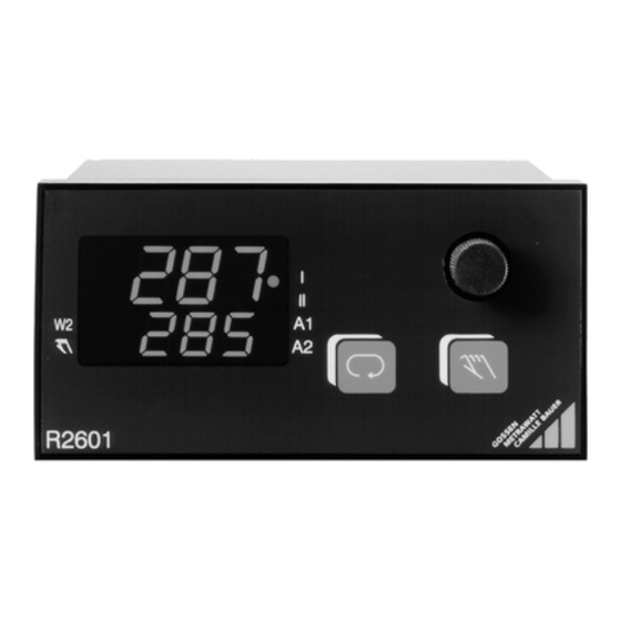
Operation Bild 5, Operating controls (arrangement for R2601) Switching output I active Switching output II active Alarm(s) active Actual value Sinkable rotary knob for setting of values Second set point active Switch-over Off/manual ↔ automatic mode Off / manual mode Switch-over displays, levels and values Set point / heating current / (see operational flow diagram) -
Page 14: Operational Flow Diagram „Switching Controller
GOSSEN-METRAWATT GMBH Operational flow diagram „Switching controller“ OPERATING LEVEL Automatic mode Extended operating level Actual value Actual value Actual value Actual value for configured differential controller see page 15 Set point Heat. curr. Reg. ratio Set point can only Appears only, when the be set here for heating current monitor PARAMETER LEVEL... -
Page 15: Operational Flow Diagram „Switching Controller" For Diff. Controller
Operational flow diagram „Switching controller“ for differential controller OPERATING LEVEL Automatic mode Act.-difference Act.-difference Act.-difference Act.-difference 1st act. value Diff. set point 2nd act. value Heat. curr. Reg. ratio The differential set point can only be set here PARAMETER LEVEL (page 28) Appears only, when the heating current monitor... -
Page 16: Operational Flow Diagram „Continuous And Step Controller
GOSSEN-METRAWATT GMBH Operational flow diagram „Continuous and step controller“ OPERATING LEVEL Manual mode Automatic mode Extended operating level Actual value Actual value Actual value for configured differential controller see page 17 Reg. ratio Set point Reg. ratio For step controller with marking A4 only Set point can only be set here for fixed value controller PARAMETER LEVEL... -
Page 17: Operat. Flow Diagr. „Cont. And Step Controller" For Diff. Controller
Operational flow diagram „Continuous and step controller“ for differential controller OPERATING LEVEL Manual mode Automatic mode Act.-difference 1st act. value Act.-difference Act.-difference Diff. set point 2nd act. value Reg. ratio Reg. ratio Differential set point For step controller can only be set here with marking A4 only PARAMETER LEVEL (page 28) -
Page 18: Off / Manual Mode
GOSSEN-METRAWATT GMBH Off / manual mode OPERATING LEVEL SWITCHING CONTROLLER – No alarm function – The positioning outputs are inactive with the rotary knob not actuated. – No error signalling – The switching output I ("heat") / II ("cool") is directly controlled by Actual value turning the knob to the right / left into the spring range OPERATING LEVEL CONTINUOUS AND STEP CONTROLLER... -
Page 19: Manual Mode With Binary Input 2
Manual mode with binary input 2 The controller can be switched to manual operation with binary input 2. This is distinguished from the Off / manual mode with the key. – Bumpless change-over to manual mode for all controller types. –... -
Page 20: Configuration
GOSSEN-METRAWATT GMBH Configuration (Cont'd on page 22) Controller type Alarms 1 Code Condition Code Startup suppression Contact Heating circuit monitor Limit monitor Relative Inactive Positioner Absolute Two-state controller Heat *) Relative Active Two-state controller Cool *) Absolute Inactive Three-state controller *) Relative Inactive Not for... - Page 21 Unit of measure of the sensor / continuous output Sensor type Code Unit meas. Output range Output quantity Code Type Kind Condition ° C 0 ... 20 mA ° F 0 ... 10 V Actual value ° C (switching controller) 4 ...
- Page 22 GOSSEN-METRAWATT GMBH Configuration (Cont'd) Function signal input 2 Standard Alarms 2 signal 2 Code B4, B5 Code Startup suppression Contact Relative Fixed value controller (internal set point) Inactive Absolute Diff. controller Fixed value contr. Diff. controller 0 ... 20 mA 0 ...
-
Page 23: Storage And Uploading Of Device Settings
Storage and Uploading of Device Settings Code Function Note Configuration according to customer specifications (K9) is stored in The current setting is stored as a user defined default setting. this location and is thus overwritten. The user defined default setting is uploaded If a setting has never previously been stored with d, the factory All entries are overwritten, including the results of self-optimization default setting, or the configuration in accordance with customer... -
Page 24: Differential Controller
GOSSEN-METRAWATT GMBH Differential controller See page 28 for Parameters – The actual value difference = 1st actual value – 2nd actual value is controlled to the set differential set point. – The differential set point can be set on the range ± range span. –... -
Page 25: Controller Types
Controller types See page 28 for Parameters Code Controller Type Remarks Switching output I is active, if act. value < actual set point, switching output II is active, if actual value > actual Limit monitor set point + dbnd. The switching hysteresis is HYST. A change of the switching state can be made every tc. Positioner Output of a constant positioning signal to switching output I, if Y ST >... -
Page 26: Configuration Of The Controller With Continuous Output (Marking A3)
GOSSEN-METRAWATT GMBH Configuration of the controller with continuous output (marking A3) Continuous output = actual value (configuration digit „Unit of measure of the sensor / continuous output“ = 0, 1, 2, 3) – The controller types act as with marking A2. –... - Page 27 Continuous output = “select with Cont” (configuration digit “Unit of measure of the sensor / continuous output” = 8, 9, A, b) Cont Contin. output Remarks The output is scaled with the parameters rn L and rn H (with differential controller the actual value difference). actual set point The controller types act same as with marking A2.
-
Page 28: Setting Parameters
GOSSEN-METRAWATT GMBH Setting parameters X1 = lower range limit, X2 = upper range limit, MBU (range span) = X2 – X1 Parameter Display Range Default Remarks High limit for relay A1 Low limit for relay A1 oFF, 1 ... MBU Relative (= standard config.) oFF, X1 ... - Page 29 High set point SP L ... X2 Low set point X1 ... SP H Maximum regulation ratio –100 ... 100 % 0 ... 100 with marking A1 Act. value calibr. (see Calibration) (Auto), –MBU/4 ... +MBU / 4 0 only with marking B1, B3, B4 •...
-
Page 30: Calibration
GOSSEN-METRAWATT GMBH Calibration Thermocouple correction (parameter CAL) This correction value is set in °C / °F. The correction value displayed is added to the measured temperature value. Lead calibration with Pt 100 two-wire connection (parameter CAL) The calibration can automatically be determined in "Off / manual mode". –... -
Page 31: Self-Optimizing
Self-optimizing Self-optimizing serves to determine optimum control dynamics that is, the parameters Pb I, Pb II, tu and tc are determined. Actual Start Getting started – Complete configuration must be made before self-optimizing is started – The set point must be set to the value required after optimizing. Slow flashing Start –... -
Page 32: Manual Optimizing
GOSSEN-METRAWATT GMBH Manual optimizing The parameters Pb I, Pb II, tu and tc are defined by manual optimizing to obtain optimum control dynamics. A trial run and an oscillation test is made for this purpose. Getting started – For the use of the controller, a complete configuration (page 20) and parameter setting (page 28) must first be made. –... - Page 33 ∆ t (only for three-state/split range controller) dbnd = MBU dbnd = 0 ∆ x Evaluation of the trial run – Apply a tangent to the curve at intersection P of actual value and set point and/or switch-off point of the output. –...
- Page 34 GOSSEN-METRAWATT GMBH Performing an oscillation test If it is not possible to perform a trial run, e.g. where adjacent control loops strongly influence the actual value, or where an active switching output is required to hold the actual value (working point of cooling), or where certain reasons require optimizing to the set point, the control parameters can be established by means of a continuous oscillation.
- Page 35 If one of the times T or T is considerably longer than the other one, the value for tu is too high. Correction with limitation of the regulation ratio Y H positive: Multiply Pb I by 100 % / Y H Y H negative: Multiply Pb II by –100 % / Y H Correction for step controller if one of the times T or T...
-
Page 36: Set Point Ramps
GOSSEN-METRAWATT GMBH Set point ramps Function The parameters SPuP / SPdn cause a gradual change in temperature (rising/falling) in degrees per minute. Activation when: – The auxiliary voltage is turned on – An actual set point is changed – The second set point is activated –... -
Page 37: Heating Circuit Monitor
Heating circuit monitor Function – Active / inactive configurable with the configuration digit "Alarms" (see Configuration) –Without external transformer, without additional parameters –Correct optimization of the control parameters tu and Pb I is a pre-condition! i.e. before self-optimization is started, heating circuit monitoring must be activated. The lower limit for the tu parameter must be maintained for manual optimization or subsequent adjustment of the control parameters: Pb I... -
Page 38: Limit Monitor
GOSSEN-METRAWATT GMBH Limit monitor Alarm relay n NOC Alarm relay n NCC n = 1, 2 Hysteresis (HYSt) Set point Actual value Limits relative ALnL ALnH ALnL ALnH Limits absolute Start-up suppression: the alarm suppression at start-up is active (configuration digit "Alarms 1") until the temperature has exceeded the low limit for the first time. -
Page 39: Alarms
Alarms Display (only on operating level) Error source Reaction Remarks Heating current flashes Heating current monitor Alarm output A1 active and LED A1 on NOC/NCC defined in the Actual value flashes Limit monitor 1 Alarm output A1 active and LED A1 on configuration digits "Alarms 1 and 2". -
Page 40: Error Messages
GOSSEN-METRAWATT GMBH Error messages Action when an error occurs: 1. Alarm output A1 is activated; configuration digit “Alarms 1” defines its action (see Configuration, page 20). 2. LED A1 flashes on all levels. Errors are only displayed (flashing) on the operating level: With incorrect measured values on the display which other- wise shows the correct value (SE H, SE L, CE and YE), the other errors are shown on the upper display. - Page 41 Self-optimizing cannot be started No reaction to error no tune (controller type "Positioner" or – Error display remains visible until a key stroke is made "Limit monitor“) Disturbed optimizing run in step 1 ... 13 Control outputs I and II inactive tune error 2 (here step 2) Self optimizing must be stopped...
-
Page 42: Technical Data
Technical data 3z / 0 / 50 Transistorized output suited for commercially available solid state relays (SSR) Climatic suitability with reference to VDI/VDE 3540 75 % Switching state No-load voltage Output current Relative humidity, annual average, no condensation Active (load ≤ 800 Ω) <...
Need help?
Do you have a question about the R2600 and is the answer not in the manual?
Questions and answers