Table of Contents

Related Manuals for WaterFurnace 506A11


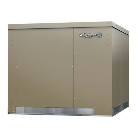
Summary of Contents for WaterFurnace 506A11
- Page 1 506A11 Geothermal Outdoor Package Heat Pump • R-410A Refrigerant • 2, 3, 4, 5, 6 Ton Dual Capacity Installation Information Water Piping Connections Electrical Startup Procedures Troubleshooting Preventive Maintenance IM2505AN 11/17...
-
Page 3: Table Of Contents
5 SERIES 506A11 OUTDOOR PACKAGED HEAT PUMP INSTALLATION MANUAL Table of Contents Model Nomenclature ............4 General Installation Information . -
Page 4: Model Nomenclature
5 SERIES 506A11 OUTDOOR PACKAGED HEAT PUMP INSTALLATION MANUAL Model Nomenclature 9-10 Model Type Packaging N – 5 Series Water-to-Air ries Wate o-Air A - Standard Compressor Type or Type D – Dual-Stage -Stage Insulation 2 - 1" Foil Faced Fiberglass... -
Page 5: General Installation Information
5 SERIES 506A11 OUTDOOR PACKAGED HEAT PUMP INSTALLATION MANUAL General Installation Information WARNING: Before performing service or maintenance operations on a system, turn off main power switches to the unit. If applicable, turn off the accessory heater power switch. Electrical Before lifting, make sure the unit weight is shock could cause personal injury. - Page 6 5 SERIES 506A11 OUTDOOR PACKAGED HEAT PUMP INSTALLATION MANUAL General Installation Information cont. Slab Mounted Units Installing Roof (Curb) Mounted Roof curb not provided by unit manufacturer and must be The unit should be set on a solid, level foundation, outsourced.
- Page 7 5 SERIES 506A11 OUTDOOR PACKAGED HEAT PUMP INSTALLATION MANUAL General Installation Information cont. Duct System Water Quality Duct flanges are provided on side air discharge units It is the responsibility of the system designer and installing to facilitate a duct connection. A flexible connector...
- Page 8 5 SERIES 506A11 OUTDOOR PACKAGED HEAT PUMP INSTALLATION MANUAL General Installation Information cont. Contaminated Water Condensate Drain In applications where the water quality cannot be held to To facilitate complete condensate removal, the outdoor prescribed limits, the use of a secondary or intermediate...
-
Page 9: Closed Loop Ground Source Systems
5 SERIES 506A11 OUTDOOR PACKAGED HEAT PUMP INSTALLATION MANUAL Closed Loop Ground Source Systems IMPORTANT: A secondary freeze detection After pressurization, be sure to turn the venting (burping) thermostat is installed in the unit to automatically screw in the center of the pump two (2) turns open (water... - Page 10 5 SERIES 506A11 OUTDOOR PACKAGED HEAT PUMP INSTALLATION MANUAL Closed Loop Ground Source Systems cont. Figure 5a: Primary/Secondary Wiring with Aurora Base Multiple Units on One Flow Center Control (no AXB Board) NOTE: This feature is only available in the Aurora Advanced...
-
Page 11: Open Loop Ground Water Systems
5 SERIES 506A11 OUTDOOR PACKAGED HEAT PUMP INSTALLATION MANUAL Open Loop Ground Water Systems Typical open loop piping is shown below. Always maintain NOTE: For open loop/groundwater systems or systems water pressure in the heat exchanger by placing water that do not contain an antifreeze solution, set SW2-Switch control valves at the outlet of the unit to prevent mineral #1 to the “WELL”... -
Page 12: Electrical Connections
5 SERIES 506A11 OUTDOOR PACKAGED HEAT PUMP INSTALLATION MANUAL Electrical Connections General Accessory Relay A set of “dry” contacts has been provided to control The heat pump, and if auxiliary heat is installed, must accessory devices, such as water solenoid valves on open have a separate electrical service with a field-supplied, loop installations, electronic air cleaners, humidifiers, etc. -
Page 13: Electronic Thermostat Installation
5 SERIES 506A11 OUTDOOR PACKAGED HEAT PUMP INSTALLATION MANUAL Electronic Thermostat Installation Position the thermostat subbase against the wall so that Figure 10: Thermostat Wiring (Y1 Style Signals) it is level and the thermostat wires protrude through the middle of the subbase. Mark the position of the... -
Page 14: Auxiliary Heat Ratings
5 SERIES 506A11 OUTDOOR PACKAGED HEAT PUMP INSTALLATION MANUAL Auxiliary Heat Ratings BTU/HR Model Size Compatibility Model Stages 208V 230V 208V 230V 036 - 042 049 - 072 EAM5* 12,300 16,300 EAM8* 19,400 25,900 EAM10* 24,600 32,700 EAL10* 24,600 32,700... -
Page 15: Electrical Data
5 SERIES 506A11 OUTDOOR PACKAGED HEAT PUMP INSTALLATION MANUAL Electrical Data Dual Capacity Unit with Variable Speed ECM Motor Blower Total Compressor Rated Voltage Model Loop Motor Unit Circ Fuse/ Voltage Min/Max LRA** HACR 208-230/60/1 187/253 18.2 11.6 58.3 21.0 21.0... -
Page 16: Blower Performance Data
5 SERIES 506A11 OUTDOOR PACKAGED HEAT PUMP INSTALLATION MANUAL Blower Performance Data Dual Capacity ECM Blower Table without Zoning AIR FLOW SPEED SETTINGS MODEL 1175 0.50 1050 1075 1275 1500 0.50 1175 1375 1450 1025 1250 2075 038 W/1HP* 0.75... - Page 17 5 SERIES 506A11 OUTDOOR PACKAGED HEAT PUMP INSTALLATION MANUAL Blower Performance Data cont. Setting Blower Speed - Variable Speed ECM Speed Setup - These screens allow the technician to select the “G”, low, high, and auxiliary heat blower speed for the ECM blower motor.
-
Page 18: Dimensional Data
5 SERIES 506A11 OUTDOOR PACKAGED HEAT PUMP INSTALLATION MANUAL Dimensional Data FRONT SIDE LEFT SIDE RIGHT SIDE BACK SIDE 038 Overall Cabinet Front Electrical Knockouts Left Electrical Knockouts Side Discharge Configuraton Width Depth Height 7/8” 1-3/8” 1-1/8” 7/8” 7/8” 1-1/8”... - Page 19 5 SERIES 506A11 OUTDOOR PACKAGED HEAT PUMP INSTALLATION MANUAL Dimensional Data cont. BOTTOM FLOW 026 BOTTOM FLOW (BACK SIDE) BLOCK OFF PLATES Bottom Side Features Bottom Flow BBB CCC EEE FFF GGG HHH Configuraton Return Loop Discharge 21.3 29.5 15.4 14.5...
- Page 20 5 SERIES 506A11 OUTDOOR PACKAGED HEAT PUMP INSTALLATION MANUAL Dimensional Data cont. 2' MINIMUM CLEARANCE FOR SERVICE ACCESS 2' MINIMUM CLEARANCE FOR SERVICE ACCESS WATER IN WATER OUT Legend Return Air Return Air Access Supply Air Control Access Panel Compressor Access Panel...
-
Page 21: Physical Data
5 SERIES 506A11 OUTDOOR PACKAGED HEAT PUMP INSTALLATION MANUAL Physical Data DUAL CAPACITY Model Compressor (1 each) Copeland UltraTech, Dual Capacity Scroll Factory Charge R410a, oz [kg] (Aluminum tube and fin air coil) 52 [1.47] 78 [2.21] 92 [2.61] 96 [2.72] 110 [3.12]... -
Page 22: The Aurora™ Control System
5 SERIES 506A11 OUTDOOR PACKAGED HEAT PUMP INSTALLATION MANUAL The Aurora™ Control System Aurora ‘Advanced’ Control Aurora ‘Base’ Control The Aurora ‘Advanced’ The Aurora ‘Base’ Control Control expands on the (ABC) System is a complete capability of the Aurora residential and commercial ‘Base’... - Page 23 5 SERIES 506A11 OUTDOOR PACKAGED HEAT PUMP INSTALLATION MANUAL The Aurora Control System cont. Service Device Description Aurora ‘Base’ Aurora 'Advanced' Allows setup, monitoring and troubleshooting of any Aurora Control. NOTE: Although the ABC has basic compatibility with all For Service...
- Page 24 5 SERIES 506A11 OUTDOOR PACKAGED HEAT PUMP INSTALLATION MANUAL The Aurora ‘Base’ Control System cont. Aurora ‘Base’ Control Field Selectable Options via Hardware DIP Switch (SW1) – Test/Configuration Button (See SW1 Operation Table) Test Mode The control is placed in the test mode by holding the push button switch SW1 for 2 - 5 seconds.
- Page 25 5 SERIES 506A11 OUTDOOR PACKAGED HEAT PUMP INSTALLATION MANUAL The Aurora ‘Base’ Control System cont. Cycle with Blower - The accessory relay will cycle with Lockout – when locked out, the blower will operate the blower output. continuously in “G” speed. The Alarm output (ALM) and Lockout output (L) will be turned on.
- Page 26 5 SERIES 506A11 OUTDOOR PACKAGED HEAT PUMP INSTALLATION MANUAL The Aurora ‘Base’ Control System cont. Secondary Freeze Detection - A freeze detection Cooling Operation thermostat is installed inside the cabinet to automatically In all cooling operations, the reversing valve directly tracks start the loop pump if temperature drops below 20˚F.
- Page 27 5 SERIES 506A11 OUTDOOR PACKAGED HEAT PUMP INSTALLATION MANUAL The Aurora ‘Base’ Control System cont. Aurora ‘Base’ Control LED Displays Aurora Interface and Diagnostics (AID) Tool These three LEDs display the status, configuration, and The Aurora Interface and fault codes for the control. These can also be read in plain Diagnostics (AID) Tool is English via the Aurora AID Tool.
- Page 28 5 SERIES 506A11 OUTDOOR PACKAGED HEAT PUMP INSTALLATION MANUAL The Aurora ‘Advanced’ Control System AWL – Aurora Weblink Aurora ‘Advanced’ Control Features (optional accessory) The Aurora ‘Advanced’ AWL is an add-on WiFi router that connects to the ABC Control system expands on...
- Page 29 5 SERIES 506A11 OUTDOOR PACKAGED HEAT PUMP INSTALLATION MANUAL The Aurora ‘Advanced’ Control System cont. Home Automation 1 and 2 Inputs Monitoring Sensor Kits The Home automation inputs are simple closed contact Energy Monitoring inputs that will trigger an AID Tool and thermostat alert for (Standard Sensor Kit on ‘Advanced’...
- Page 30 5 SERIES 506A11 OUTDOOR PACKAGED HEAT PUMP INSTALLATION MANUAL The Aurora ‘Advanced’ Control System cont. Special Modes and Applications Aurora ‘Advanced’ Control LED Displays Communicating Digital Thermostats These three LEDs display the status, configuration, and fault The Aurora controls system also features either mono- codes for the control.
-
Page 31: Reference Calculations And Legend
5 SERIES 506A11 OUTDOOR PACKAGED HEAT PUMP INSTALLATION MANUAL Reference Calculations Heating Calculations: Cooling Calculations: LWT = EWT + LWT = EWT - gpm x 500 gpm x 500 LAT (DB) = EAT (DB) - LAT = EAT + cfm x 1.08 cfm x 1.08... -
Page 32: Wiring Schematics
5 SERIES 506A11 OUTDOOR PACKAGED HEAT PUMP INSTALLATION MANUAL Wiring Schematics Aurora Base Controls with ECM and IntelliStart Green/Yellow For optional Flow Center and Water Valve For optional IntelliStart wiring schematics refer to Blue wiring schematics refer to appropriate schematic. - Page 33 5 SERIES 506A11 OUTDOOR PACKAGED HEAT PUMP INSTALLATION MANUAL Wiring Schematics cont. Aurora Base Controls with ECM and IntelliStart cont. With optional EA Series 10kW Auxiliary Electric Heat Shown 1 - Use copper o r aluminum conductors. 208-230/60/1 2 – When Auxil iary Heat is installe d the BLK/WHT...
- Page 34 5 SERIES 506A11 OUTDOOR PACKAGED HEAT PUMP INSTALLATION MANUAL Wiring Schematics cont. Aurora Base Controls with ECM and IntelliStart FP1 – 15 F/30 ECM PWM FP2 – 15 F/30 ABC SW2 Accessory Relay RV – B/O Fault DESCRIPTION SW2-4 SW2-5 Config ACC –...
- Page 35 5 SERIES 506A11 OUTDOOR PACKAGED HEAT PUMP INSTALLATION MANUAL Wiring Schematics cont. Aurora Base Controls with ECM and IntelliStart Wiring For Op onal IntelliStart Op on Internal Water Valve Blue Compresso r Or ange (29) Run Winding IntelliStart Blue Black/White (31)
- Page 36 5 SERIES 506A11 OUTDOOR PACKAGED HEAT PUMP INSTALLATION MANUAL Wiring Schematics cont. Aurora Advanced Controls with ECM and IntelliStart Green/Yellow For op onal Flow Center and Water For op onal IntelliStart wiring Blue Valve wiring schema cs refer to the...
- Page 37 5 SERIES 506A11 OUTDOOR PACKAGED HEAT PUMP INSTALLATION MANUAL Wiring Schematics cont. Aurora Advanced Controls with ECM and IntelliStart cont. With optional EA Series 20kW Auxiliary Electric Heat Shown 60 AMP 60 AMP Legend BRK2 BRK1 Factory Low voltage wi ri ng...
- Page 38 5 SERIES 506A11 OUTDOOR PACKAGED HEAT PUMP INSTALLATION MANUAL Wiring Schematics cont. Aurora Advanced with ECM and IntelliStart FP1 – 15 F/30 ECM PWM FP2 – 15 F/30 RV – B/O Fault Config ACC – Dip 4 ACC – Dip 5 CC –...
- Page 39 5 SERIES 506A11 OUTDOOR PACKAGED HEAT PUMP INSTALLATION MANUAL Wiring Schematics cont. Aurora Advanced with ECM and IntelliStart cont. IntelliStart Op on Blue Compresso r Run W inding IntelliStart Blue Active Black Pink Start Tan(6) Common Black Unit Power Supply...
-
Page 40: Unit Startup
5 SERIES 506A11 OUTDOOR PACKAGED HEAT PUMP INSTALLATION MANUAL Unit Startup i. Brine Selection – for HE/HR Before Powering Unit, Check the Following: capacity calculation NOTE: Remove and discard the compressor hold down ii. Flow Meter – activates the flow meter shipping bolt located at the front of the compressor iii. - Page 41 5 SERIES 506A11 OUTDOOR PACKAGED HEAT PUMP INSTALLATION MANUAL Unit Startup cont. iii. In the Sensor Kit Setup screen adjust the Performance Monitoring (optional sensor kit) ‘Base Voltage’ to the nearest value to that The optional Performance Monitoring Kit includes three...
-
Page 42: Antifreeze Corrections
5 SERIES 506A11 OUTDOOR PACKAGED HEAT PUMP INSTALLATION MANUAL Unit Startup cont. 14. If auxiliary electric heaters are installed, increase the heating setpoint until the electric heat banks are sequenced on. All stages of the auxiliary heater should be sequenced on when the thermostat is in the Emergency Heat mode. -
Page 43: Correction Factor Tables
5 SERIES 506A11 OUTDOOR PACKAGED HEAT PUMP INSTALLATION MANUAL Correction Factor Tables Air Flow Corrections (Dual Capacity Part Load) Airflow Cooling Heating cfm Per Ton % of Nominal Total Cap Sens Cap Power Heat of Rej Htg Cap Power Heat of Ext of Clg 0.922... -
Page 44: Operating Parameters
5 SERIES 506A11 OUTDOOR PACKAGED HEAT PUMP INSTALLATION MANUAL Operating Parameters Dual Capacity Models First Stage Operation Cooling -- No Hot Water Generation Entering Water Water Flow Suction Pressure Discharge Pressure Water Temp Rise Air Temp Drop Temp °F gpm/ton... -
Page 45: Pressure Drop
5 SERIES 506A11 OUTDOOR PACKAGED HEAT PUMP INSTALLATION MANUAL Pressure Drop Dual Capacity Pressure Drop (psi) Model 30°F 50°F 70°F 90°F 110°F full load part load full load part load full load part load full load part load full load... -
Page 46: Compressor And Thermistor Resistance
5 SERIES 506A11 OUTDOOR PACKAGED HEAT PUMP INSTALLATION MANUAL Compressor Resistance Thermistor Resistance Thermistor Microprocessor 208-230/60/1 Compressor Model Temperature (°F) Resistance (Ohms) Model No. Start 75757-70117 ZPS20K5E-PFV 1.21 - 1.39 1.52 - 1.75 57392-53234 ZPS30K5E-PFV 0.81 - 0.94 1.41 - 1.63... -
Page 47: Heat Of Extraction/Rejection
5 SERIES 506A11 OUTDOOR PACKAGED HEAT PUMP INSTALLATION MANUAL Heat of Extraction/Rejection Dual Capacity Heat of Extraction (kBtuh) Heat of Rejection (kBtuh) Model 30°F 50°F 70°F 90°F 30°F 50°F 70°F 90°F 110°F 12.8 10.8 14.7 22.8 21.4 20.3 Part 13.3 11.3... -
Page 48: Troubleshooting
5 SERIES 506A11 OUTDOOR PACKAGED HEAT PUMP INSTALLATION MANUAL Troubleshooting Aurora Control System Refrigerant Systems NOTE: Refer to the Aurora Base Control Application and To maintain sealed circuit integrity, do not install service Troubleshooting Guide and the Instruction Guide: Aurora gauges unless unit operation appears abnormal. - Page 49 5 SERIES 506A11 OUTDOOR PACKAGED HEAT PUMP INSTALLATION MANUAL Troubleshooting cont. Water Leaving Water Blower Thermistor Coax Coil Flow Sensor Water Flow Meter Entering Water Thermistor Leaving Air Thermistor Wire Bundle In FP2 Sensor Blower Performance Option Only Compartment) Water Line View of Coax...
- Page 50 5 SERIES 506A11 OUTDOOR PACKAGED HEAT PUMP INSTALLATION MANUAL Startup/ roubleshooting Form Controls Info: Dealer: ABC Version: AXB Version: Phone #: Date: IZ2 Version: Problem: T-Stat Version: Model #: Installed Sensors: Serial #: COOLING CYCLE ANALYSIS SAT °F °F Unit Amp Draw:...
- Page 51 5 SERIES 506A11 OUTDOOR PACKAGED HEAT PUMP INSTALLATION MANUAL Troubleshooting cont. Single Speed/Dual Capacity Startup/Troubleshooting Form 1. Job Information Model # Job Name: Loop: Open / Closed Serial # Install Date: Hot Water Generator: Y / N 2. Flow Rate in gpm...
-
Page 52: Preventive Maintenance
5 SERIES 506A11 OUTDOOR PACKAGED HEAT PUMP INSTALLATION MANUAL Preventive Maintenance Water Coil Maintenance Other Maintenance Filters Keep all air out of the water. An open loop system should be checked to ensure that the well head is not Filters must be clean to obtain maximum performance. -
Page 53: Service Parts List
5 SERIES 506A11 OUTDOOR PACKAGED HEAT PUMP INSTALLATION MANUAL Service Parts List Dual Capacity Units Parts List Compressor 208-230/60/1 34P640-01 34P641-01 34P642-01 34P643-01 34P644-01 Run Capacitor 208-230/60/1 16P002D19 16P002D20 16P002D18 16P002D31 16P002D31 Sound Jacket 92P504A16 92P504A16 92P504A16 92P504A16 92P504A16 Power Harness... - Page 54 5 SERIES 506A11 OUTDOOR PACKAGED HEAT PUMP INSTALLATION MANUAL Notes...
- Page 55 5 SERIES 506A11 OUTDOOR PACKAGED HEAT PUMP INSTALLATION MANUAL Revision Guide Pages: Description: Date: Document Created Nov. 23 2017 JM/MA...
- Page 56 Installation Manual ISO 17025 Accredited ©2017 WaterFurnace International, Inc., 9000 Conservation Way, Fort Wayne, IN 46809-9794. WaterFurnace has a policy IM2505AN 11/17 of continual product research and development and reserves the right to change design and specifi cations without notice.
Need help?
Do you have a question about the 506A11 and is the answer not in the manual?
Questions and answers