Table of Contents
Advertisement
Quick Links
Advertisement
Table of Contents
Troubleshooting

Related Manuals for WaterFurnace Envision2 Compact


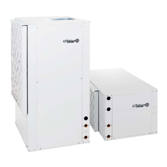
Summary of Contents for WaterFurnace Envision2 Compact
- Page 1 COMPACT Water Source/Geothermal Heat Pump - 50 Hz • R-410A Refrigerant • Commercial 005 to 017 kW Installation Information Water Piping Connections Hot Water Connections Electrical Startup Procedures Troubleshooting Preventive Maintenance IM1025AN 01/15...
-
Page 3: Table Of Contents
ENVISION COMPACT - 50 HZ INSTALLATION MANUAL Table of Contents Model Nomenclature ............. . . 4 General Installation Information . -
Page 4: Model Nomenclature
ENVISION COMPACT - 50 HZ INSTALLATION MANUAL Model Nomenclature 22-23 Model Type Vintage NBK – Envision * - Factory Use Only Compact 50Hz Non-Standard Options Cabinet Configuration SS – Standard V – Vertical H - Horizontal Drain Pan Option 0 – Composite, No Secondary Connection Unit Capacity (kW) 1 –... -
Page 5: General Installation Information
ENVISION COMPACT - 50 HZ INSTALLATION MANUAL General Installation Information Unit Location Safety Considerations Locate the unit in an indoor area that allows for easy WARNING: Before performing service or removal of the filter and access panels. Location should maintenance operations on a system, turn off main have enough space for service personnel to perform power switches to the indoor unit. -
Page 6: Dimensional Data
ENVISION COMPACT - 50 HZ INSTALLATION MANUAL Vertical Dimensional Data Standard filter rails for Field installed open return applications duct flange Deluxe filter rack for ductable return applications Air coil ACCESS PANEL 2' (61 cm) Alternate Service Access FRONT FRONT 1.4 in (3.5 cm) 1.4 in (3.5 cm) Top View - Right Return... - Page 7 ENVISION COMPACT - 50 HZ INSTALLATION MANUAL Vertical Dimensional Data cont. Electrical Knockouts Overall Cabinet Water Connections Vertical 12.7 mm 12.7 mm Loop Knockout 25.4 mm Models cond cond Cond- Water Low Volt- Low Volt- Power Width Depth Height* HWG In HWG Out Provi- ensate Supply...
-
Page 8: Horizontal Dimensional Data
ENVISION COMPACT - 50 HZ INSTALLATION MANUAL Horizontal Dimensional Data 1.7 in. 1.7 in. Standard filter rails [5.3 cm] [5.3 cm] Standard filter rails 1 in. [2.5 cm] knockout Left Return 0.5 in. [1.3 cm] knockout Right Return Front Front RR Front View 2' (61 cm) 2' (61 cm) - Page 9 ENVISION COMPACT - 50 HZ INSTALLATION MANUAL Horizontal Dimensional Data cont. Water Connections Electrical Knockouts Overall Cabinet Horizontal Loop Models 12.7 mm cond 25.4 mm Water FPT Width Depth Height* Condensate Low Voltage Power Supply 005 cm 57.2 106.7 48.8 17.3 19.05 mm 23.1...
-
Page 10: Installing Horizontal Units
ENVISION COMPACT - 50 HZ INSTALLATION MANUAL Installing Horizontal Units Installing Horizontal Units allow filter access, install hanger brackets as illustrated in the Hanger Bracket Locations section. The unit should be Remove and discard the compressor hold down shipping pitched approximately 6.35 mm towards the drain in both bolt located at the front of the compressor mounting directions to facilitate the removal of condensate. -
Page 11: Hanger Bracket Locations
ENVISION COMPACT - 50 HZ INSTALLATION MANUAL Hanger Bracket Locations Right Left Compressor Section Air Handler Section Air Handler Section Compressor Section 3/8” Vibration Isolator Threaded Rod (not supplied) Washer Hex Nuts (not supplied) Bolt and Lockwasher NOTE: Model size 017 will be shipped with six (6) hanger brackets. Only five(5) hanger brackets will be used on the unit. See the above illustration for the fifth hanger bracket location. -
Page 12: Duct System
ENVISION COMPACT - 50 HZ INSTALLATION MANUAL Duct System An air outlet collar is provided on vertical top flow units The duct system should be sized to handle the design and all horizontal units to facilitate a duct connection. airflow quietly and efficiently. To maximize sound A flexible connector is recommended for discharge attenuation of the unit blower, the supply and return and return air duct connections on metal duct systems. -
Page 13: Water Quality
ENVISION COMPACT - 50 HZ INSTALLATION MANUAL Water Quality In ground water situations where scaling could be heavy with extremely hard water, the owner should be informed or where biological growth such as iron bacteria will be that the heat exchanger may require occasional flushing. present, a closed loop system is recommended. -
Page 14: Open Loop Ground Water Systems
ENVISION COMPACT - 50 HZ INSTALLATION MANUAL System Cleaning and Flushing cont. be opened for initial flush and blowdown, making sure been established through all components including the water fill valves are set at the same rate. Check the pressure heat rejector (regardless of season), air vented and loop gauge at the pump suction and manually adjust the make- temperatures stabilized, each of the units will be ready for... -
Page 15: Hot Water Generator Connections
ENVISION COMPACT - 50 HZ INSTALLATION MANUAL Hot Water Generator Connections The heat reclaiming hot water generator coil is of vented Typical Hot Water Generator Installation double-wall copper construction and is suitable for Cold 19.1mm x 19.1mm x 12.7mm Tee potable water. - Page 16 ENVISION COMPACT - 50 HZ INSTALLATION MANUAL Hot Water Generator Connections cont. 9. After the thermostat(s) is adjusted, replace the access Hot Water Generator Startup cover and restore electrical supply to the water heater. 1. Make sure the power is off to the heat pump. Connect 10.
-
Page 17: Freeze Detection
ENVISION COMPACT - 50 HZ INSTALLATION MANUAL Freeze Detection For Aurora Base Control, set SW2-1, FP1, on the printed For FX10 board, the “red” wire must be removed from PB2-3 circuit board for applications using a closed loop antifreeze to change from -1.1°C, the factory default setting, to -9.4°C. solution to -9.4°C. -
Page 18: Electrical Data
ENVISION COMPACT - 50 HZ INSTALLATION MANUAL Electrical Data 5-Speed Motor Compressor Blower Total Rated Voltage Model Motor Unit Circ Fuse/HACR Voltage Min/Max LRA* Breaker 220-240/50/1 198/264 13.1 24.0 11.0 220-240/50/1 198/264 38.2 24.5 153.0 61.2 32.1 38.2 380-420/50/3 342/462 13.3 67.1 40.3... -
Page 19: Blower Performance Data
ENVISION COMPACT - 50 HZ INSTALLATION MANUAL Blower Performance Data 5-Speed ECM Blower Motor Airflow (L/s) at External Static Pressure (Pa) Motor T’Stat Blower Motor Model Motor Spd Cnct. Size 12.45 24.90 37.35 49.80 62.25 74.70 87.15 99.60 112.05 124.50 149.40 174.30 199.20 224.10 249.00 High Med High 229 x 178... - Page 20 ENVISION COMPACT - 50 HZ INSTALLATION MANUAL Blower Performance Data cont. Variable Speed ECM Motor Airflow DIP Switch Settings Blower Motor Model ESP (Pa) Size 124.50 229 x 178 0.37 124.50 229 x 178 0.37 124.50 279 x 254 0.37 124.50 279 x 254 0.37...
-
Page 21: Wiring Schematics
ENVISION COMPACT - 50 HZ INSTALLATION MANUAL Wiring Schematics Aurora UPC To ABC - P8 1 2 3 4 5 6 7 8 Orange Blue Green White Brown Black Yellow BACnet or N2 Network Connections Devices Must Be Wired in Daisy Chain Configuration Optional LON Add-On Module... - Page 22 ENVISION COMPACT - 50 HZ INSTALLATION MANUAL Wiring Schematics cont. Commercial Aurora, UPC with X13 Motor – 380-420/50/31 Note 4 Black Phase Yellow Guard Monitor Unit Power Supply (PGM) 380-420/50/3 L1 L2 L3 Note 1 Red (9) Green (93) Ground Neutral White (8) Disconnect...
- Page 23 ENVISION COMPACT - 50 HZ INSTALLATION MANUAL Wiring Schematics cont. Commercial Aurora, UPC with X13 Motor – 380-420/50/31 Legend Notes: Factory Low Voltage Wiring Thermistor Factory Line Voltage Wiring 1 – Optional, factory installed unit mounted disconnect. Field Low Voltage Wiring Relay Coil 2 –...
- Page 24 ENVISION COMPACT - 50 HZ INSTALLATION MANUAL Wiring Schematics cont. Commercial Aurora with X13 Motor – 380-420/50/31 Note 4 Black Phase Yellow Guard Monitor Unit Power Supply (PGM) 380-420/50/3 L1 L2 L3 Note 1 Red (9) Green (93) Ground Neutral White (8) Disconnect Black (7)
- Page 25 ENVISION COMPACT - 50 HZ INSTALLATION MANUAL Wiring Schematics cont. Commercial Aurora with X13 Motor – 380-420/50/31 Legend Notes: Factory Low Voltage Wiring Thermistor Factory Line Voltage Wiring Field Low Voltage Wiring 1 – Optional, factory installed unit mounted disconnect. Relay Coil Field Line Voltage Wiring 2 –...
- Page 26 ENVISION COMPACT - 50 HZ INSTALLATION MANUAL Wiring Schematics cont. Aurora Base Control 420/50/3 Variable Speed ECM Compressor Unit Power Supply 380-420/50/3 w/Neutral Note 3 Phase Yellow Black Guard Orange Monitor Note 1 (PGM) Brown L1 L2 L3 Green (93) Ground Gray (94) Neutral...
- Page 27 ENVISION COMPACT - 50 HZ INSTALLATION MANUAL Wiring Schematics cont. Aurora Base Control 420/50/3 Variable Speed ECM Accessory Relay Operation SW2-4 SW2-5 Cycle with Blower Cycle with Compressor Water Valve Slow Open Outdoor Air Damper Aurora Timing Events Event Normal Mode Test Mode Random Start Delay 5 to 80 seconds...
-
Page 28: Controls
ENVISION COMPACT - 50 HZ INSTALLATION MANUAL Controls - Aurora Base Control Aurora Base Control Field Selectable Options via Hardware DIP Switch (SW1) – Test/Configuration Button (See SW1 Operation Table) Test Mode The control is placed in the test mode by holding the push button switch SW1 for 2 - 5 seconds. -
Page 29: Safety Features
ENVISION COMPACT - 50 HZ INSTALLATION MANUAL Controls - Aurora Base Control cont. Anti-Short Cycle Protection – 4 minute anti-short cycle Access Relay Operation SW2-4 SW2-5 protection for the compressor. Cycle with Blower Cycle with Compressor Random Start – 5 to 80 second random start upon power up. Water Valve Slow Opening (Reserved) Fault Retry –... - Page 30 ENVISION COMPACT - 50 HZ INSTALLATION MANUAL Controls - Aurora Base Control cont. Condensate Overflow - fault is recognized when the emergency heat demand is not satisfied after 2 minutes the impedance between this line and 24 VAC common or chassis second electric heat stage will be energized.
- Page 31 ENVISION COMPACT - 50 HZ INSTALLATION MANUAL Controls - Aurora Base Control cont. Load Shed Aurora Interface and Design (AID) Tool The LS input disables all outputs with the exception of The Aurora Interface and the blower output. When the LS input has been cleared, Diagnostics (AID) Tool is the anti-short cycle timer and random start timer will be a device that is a member...
- Page 32 ENVISION COMPACT - 50 HZ INSTALLATION MANUAL Controls - UPC DDC Control (optional) Aurora UPC Controller ZS Series Sensors The Aurora Unitary Protocol Converter (UPC) is designed and communicate to the heat pump thru a choice of 3 to add-on to any Aurora based heat pump control. The different communication protocols.
- Page 33 ENVISION COMPACT - 50 HZ INSTALLATION MANUAL Controls - UPC DDC Control (optional) cont. Modbus BACnet LonWorks Rnet Aurora UPC Features Aurora UPC Optional Features • Rugged enclosure made of GE C2950 Cycoloy plastic • BACview handheld display, needed for field configuration •...
- Page 34 ENVISION COMPACT - 50 HZ INSTALLATION MANUAL Controls - UPC DDC Control (optional) cont. Port 1a is used to communicate to the Building Automation System (BAS). This port’s settings are configured through 24Vac the onboard dip switches. Port 2 is used to com- municate to the Au- Dip switches for rora Base Controller...
- Page 35 ENVISION COMPACT - 50 HZ INSTALLATION MANUAL Controls - UPC DDC Control (optional) cont. Leaving Air Temperature (LAT) Sensor – This 10 kOhm Dirty Filter Switch – This optional field installed switch NTC sensor is factory installed on all UPC equipped is connected to confirm dirty filter operation.
- Page 36 ENVISION COMPACT - 50 HZ INSTALLATION MANUAL Controls - UPC DDC Control (optional) cont. Aurora Base or Advanced Control Configuration and Status Codes Status LED (LED3, Green) Description of Operation Fault LED, Green Normal Mode Control is Non-functional Test Mode Slow Flash Lockout Active Fast Flash...
- Page 37 ENVISION COMPACT - 50 HZ INSTALLATION MANUAL Controls - UPC DDC Control (optional) cont. Aurora Advanced Control Configuration and Options (Future Availability on Select Models/Configurations) Accessory Relay2 – A second, configurable, accessory relay on the AXB is provided that can be cycled with the compressor 1 or 2 , blower, or the Dehumidifier (DH) input.
- Page 38 ENVISION COMPACT - 50 HZ INSTALLATION MANUAL Controls - UPC DDC Control (optional) cont. Aurora Advanced Control Optional Sensor Kits (Future Availability on Select Models/Configurations) Energy Monitoring (Standard Sensor Kit on Performance Monitoring (optional sensor kit) - The ‘Advanced’ models) - The Energy Monitoring Kit optional Performance Monitoring Kit includes: three includes two current transducers (blower and electric temperature sensors, entering and leaving water,...
- Page 39 ENVISION COMPACT - 50 HZ INSTALLATION MANUAL Controls - UPC DDC Control (optional) cont. ZS Series RNet Sensor Overview This is done using (2) 18 AWG twisted pair unshielded cables for a total of 4 wires connected to the Rnet port. The ZS Series line of intelligent zone sensors provides the The sensor gets its power from the UPC controller and function and flexibility you need to manage the conditions...
- Page 40 ENVISION COMPACT - 50 HZ INSTALLATION MANUAL Controls - UPC DDC Control (optional) cont. RNet Sensor Physical and Electrical Data Sensing Element Range Accuracy Temperature (on non-Humidity models) -4° to 122° F (-20° C to 50° C) ±0.35° F (0.2° C) Temperature (on Humidity models) 50°...
-
Page 41: Unit Startup
ENVISION COMPACT - 50 HZ INSTALLATION MANUAL Unit Startup Before Powering Unit, Check The Following: NOTE: Remove and discard the compressor shipping bolts. The bolts can then be discarded. • High voltage is correct and matches nameplate. • Fuses, breakers and wire size correct. •... -
Page 42: Operating Limits
ENVISION COMPACT - 50 HZ INSTALLATION MANUAL Operating Limits Operating Limits Cooling (°C) Heating (°C) Air Limits Min. Ambient Air Rated Ambient Air 26.7 21.1 Max. Ambient Air 37.8 29.4 Min. Entering Air 10.0 NOTE: Minimum/maximum limits are only for startup conditions, and Rated Entering Air db/wb 27/19 20.0... -
Page 43: Operating Parameters
ENVISION COMPACT - 50 HZ INSTALLATION MANUAL Operating Parameters cont. Dual Capacity Models First Stage Operation Cooling -- No Hot Water Generation Entering Water Water Flow Suction Pressure Discharge Water Temp Rise Air Temp Drop Temp °C L/s per kW Superheat Subcooling Pressure kPa... -
Page 44: Pressure Drop
ENVISION COMPACT - 50 HZ INSTALLATION MANUAL Pressure Drop Pressure Drop (kPa) Pressure Model Valve Drop (kPa) -1.11°C 10°C 21.1°C 32.2°C 43.3°C 0.19 11.0 11.0 10.3 10.3 0.19 0.63 0.25 20.0 20.0 19.3 19.3 18.6 0.25 10.1 1.10 3/4” 0.32 29.0 29.0 28.3... -
Page 45: Reference Calculations And Legend
ENVISION COMPACT - 50 HZ INSTALLATION MANUAL Reference Calculations Heating Calculations: Cooling Calculations: LWT = EWT + LWT = EWT - WF x 500 WF x 500 LAT (DB) = EAT (DB) - LAT = EAT + AF x 1.08 AF x 1.08 LC = TC - SC TH = HC + HW... -
Page 46: Refrigerant Circuit Guideline
ENVISION COMPACT - 50 HZ INSTALLATION MANUAL Refrigerant Circuit Guideline Head Suction Compressor Air Temp. Water Temp. Symptom Superheat Subcooling Pressure Pressure Amp Draw Differential Differential Under Charged System (Possible Leak) High Over Charged System High High High Normal High Normal/Low Normal Low Air Flow Heating... -
Page 47: Heat Of Extraction/Rejection Data
ENVISION COMPACT - 50 HZ INSTALLATION MANUAL Heat of Extraction/Rejection Data Heat of Extraction (kW) Heat of Rejection (kW) Model -1.11°C 10°C 21.1°C 32.2°C -1.11°C 10°C 21.1°C 32.2°C 43.3°C 0.19 3.34 4.07 5.60 6.74 6.33 Full Load 0.25 2.96 3.58 4.34 5.71 6.83... -
Page 48: Troubleshooting
ENVISION COMPACT - 50 HZ INSTALLATION MANUAL Troubleshooting Should a major problem develop, refer to the following If the unit operation is noisy: information for possible causes and corrective steps. Check compressor for loosened mounting bolts. Make sure compressor is floating free on its isolator mounts. Check for tubing contact with the compressor or other If compressor won’t run: surfaces. -
Page 49: Startup And Troubleshooting Form
ENVISION COMPACT - 50 HZ INSTALLATION MANUAL Startup and Troubleshooting Form Company Name: _________________________________ Company Phone No: ______________________________ Technician Name: ________________________________ Date: __________________________________________ Model No: ______________________________________ Serial No:_______________________________________ Owner’s Name: __________________________________ Open or Closed Loop: _____________________________ Installation Address: ______________________________ Installation Date: _________________________________ Check One Start up/Check-out for new installation Troubleshooting... -
Page 50: Heating/Cooling Cycle Analysis
ENVISION COMPACT - 50 HZ INSTALLATION MANUAL Heating Cycle Analysis ______kPa = ______SAT°C ______°C Suction Compressor Load Source Discharge Coax Coax ______kPa = ______SAT°C ______°C ______°C Liquid Line Entering Source Water °C Entering Water Pressure Leaving Source Water °C Leaving Water Pressure Unit Amp Draw Line Voltage Entering Load Water... -
Page 51: Preventive Maintenance And Replacement Parts
ENVISION COMPACT - 50 HZ INSTALLATION MANUAL Preventive Maintenance Condensate Drain Water Coil Maintenance In areas where airborne bacteria produce a slime in the Keep all air out of the water. An open loop system drain pan, it may be necessary to treat chemically to should be checked to ensure that the well head is not minimize the problem. -
Page 52: Service Parts
ENVISION COMPACT - 50 HZ INSTALLATION MANUAL Service Parts Single Speed Vertical Units Dual Capacity Vertical Units Part Description Compressor 220-240/50/1 34P593-03 34P561-09 34P640-02 34P641-02 34P642-02 34P643-01 Compressor 380-420/50/3 34P646-04 34P640-04 34P641-04 34P642-04 34P643-04 Run Capacitor 220-240/50/1 16P002D30 16P002D33 16P002D20 16P002D23 16P002D24 16P002D39... -
Page 53: Revision Guide
ENVISION COMPACT - 50 HZ INSTALLATION MANUAL Revision Guide Pages: Description: Date: Released UPC Control Option 19 Jan 2015 Updated with All-Aluminum Air Coils 21 May 2014 Updated Compressor LRA with IntelliStart 31 Jul 2013 Updated Nomenclature to Reflect new ECM Blower Motor 06 Nov 2012 Updated Service Parts List for New ECM Blower Part Numbers 06 Nov 2012... - Page 54 Commercial 005-017 kW Document: Installation Manual IM1022AN 01/15 ©2015 WaterFurnace International, Inc., 9000 Conservation Way, Fort Wayne, IN 46809-9794. WaterFurnace has a policy of continual product research and development and reserves the right to change design and specifi cations without notice.
Need help?
Do you have a question about the Envision2 Compact and is the answer not in the manual?
Questions and answers