Table of Contents
Advertisement
Quick Links
Download this manual
See also:
Instruction Book
Advertisement
Table of Contents

Related Manuals for BIRD ECONOLOAD 8730 Series


Summary of Contents for BIRD ECONOLOAD 8730 Series
- Page 1 ® ECONOLOAD LOAD RESISTOR SERIES 8730 INCLUDING MODELS 8730A, 8731 8732A, 8738A, AND 8738A110 Operation Manual ©Copyright 2016 by Bird Technologies , Inc. Instruction Book P/N 920-8730S Rev. D Econoload and Termaline are Registered Trademarks of Bird Electronic Corporation...
-
Page 2: Safety Precautions
Safety Precautions The following are general safety precautions that are not necessarily related to any specific part or procedure, and do not necessarily appear elsewhere in this publication. These precautions must be thoroughly understood and apply to all phases of operation and maintenance. WARNING Keep Away From Live Circuits Operating Personnel must at all times observe general safety precautions. -
Page 3: Safety Symbols
Safety Precautions Safety Symbols WARNING Warning notes call attention to a procedure, which if not correctly performed, could result in personal injury. CAUTION Caution notes call attention to a procedure, which if not correctly performed, could result in damage to the instrument. This symbol indicates that a shock hazard exists if the precautions in the instruction manual are not followed. -
Page 4: Warning Statements
Econoload® Load Resistor Warning Statements The following safety warnings appear in the text where there is danger to operating and maintenance personnel, and are repeated here for emphasis. WARNING Disconnect the unit from all power sources before servicing. The unit may be energized from multiple sources. -
Page 5: Caution Statements
Safety Precautions Caution Statements The following equipment cautions appear in the text and are repeated here for emphasis. CAUTION Incorrect hose connections will reverse coolant flow and could destroy the load. On page 4. CAUTION If installed, connect optional interlock before applying RF power. On pages 5, 6 and 9. -
Page 6: Safety Statements
Econoload® Load Resistor Safety Statements USAGE ANY USE OF THIS INSTRUMENT IN A MANNER NOT SPECIFIED BY THE MANUFACTURER MAY IMPAIR THE INSTRUMENT’S SAFETY PROTECTION. EL USO DE ESTE INSTRUMENTO DE MANERA NO ESPECIFICADA POR EL FABRICANTE, PUEDE ANULAR LA PROTECCIÓN DE SEGURIDAD DEL INSTRUMENTO. BENUTZUNG WIRD DAS GERÄT AUF ANDERE WEISE VERWENDET ALS VOM HERSTELLER BESCHRIEBEN, KANN DIE GERÄTESICHERHEIT BEEINTRÄCHTIGT WERDEN. - Page 7 Safety Precautions SERVICE SERVICING INSTRUCTIONS ARE FOR USE BY SERVICE - TRAINED PERSONNEL ONLY. TO AVOID DANGEROUS ELECTRIC SHOCK, DO NOT PERFORM ANY SERVICING UNLESS QUALIFIED TO DO SERVICIO LAS INSTRUCCIONES DE SERVICIO SON PARA USO EXCLUSIVO DEL PERSONAL DE SERVICIO CAPACITADO.
- Page 8 Econoload® Load Resistor CONNECT INTERLOCK TO TRANSMITTER BEFORE OPERATING. BRANCHER LE VERROUILLAGE À L'ÉMETTEUR AVANT EMPLOI. CONECTE EL INTERBLOQUEO AL TRANSMISOR ANTES DE LA OPERACION. VOR INBETRIEBNAHME VERRIEGELUNG AM SENDER ANSCHLIESSEN. PRIMA DI METTERE IN FUNZIONE L'APPARECCHIO, COLLEGARE IL DISPOSITIVO DI BLOCCO AL TRASMETTITORE.
-
Page 9: About This Manual
About This Manual About This Manual This manual covers the operating and maintenance instructions for the following models: 8730A 8731 8738A 8732A 8738A110 Changes to this Manual We have made every effort to ensure this manual is accurate. If you discover any errors, or if you have suggestions for improving this manual, please send your comments to our Solon, Ohio factory. -
Page 10: Table Of Contents
Table of Contents Safety Precautions ..............i Safety Symbols . - Page 11 Bird 8730A, 8732A, and 8738A ........
-
Page 12: Chapter 1 Introduction
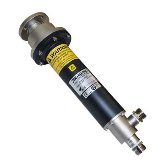
They dissipate up to 10 kW with a VSWR of less than 1.1:1 from 1 kHz to 1000 MHz. Features Useable with CW, AM, FM, SSB, and TV modulation, and certain pulse types. Contact Bird for information on using Econoloads with pulsed signals. ... - Page 13 Introduction Figure 1 8730 Series Econoload Outline Drawing...
-
Page 14: Chapter 2 Theory Of Operation
Theory Of Operation Resistor Bird 8730 Series Econoloads consist of a thin-film-on-ceramic resistor immersed in externally-supplied coolant. The coolant flows directly over the resistor instead of using an intermediate heat transfer system, reducing the load size to a minimum. After passing over the entire length of the resistor, the coolant leaves the load and can either be discarded or cooled in a heat exchanger and reused. -
Page 15: Chapter 3 Installation
Chapter 3 Installation This chapter provides information on site requirements, unpacking, inspection, and preparing the Bird 8730 Series Econoload for use. Unpacking and Inspection 1. Carefully inspect shipping container for signs of damage. If the shipping container is damaged, do not unpack the unit. Immediately notify the shipping carrier and Bird Technologies. -
Page 16: Interlock (Optional)
Econoload® Load Resistor Interlock (Optional) WARNING Disconnect the unit from all power sources before servicing. The unit may be energized from multiple sources. The potential for electric shock exists. WARNING Improper wiring could result in electric shock and death. CAUTION If installed, connect optional interlock before applying RF power. -
Page 17: Thermoswitch (8732A Only) (Optional)
Installation Thermoswitch (8732A Only) (Optional) Installing the Thermoswitch CAUTION If installed, connect optional interlock before applying RF power. Note: The 8732A, only, can be equipped with an optional interlock thermoswitch, P/N 2450-095-x. 1. Stand the unit with the water connectors up to prevent spills. 2. -
Page 18: Connecting The Rf Power
Econoload® Load Resistor Connecting the RF Power After installing the Econoload, the RF transmission line can be attached using standard coaxial line coupling kits. WARNING Never attempt to connect or disconnect RF equipment from the transmission line while RF power is being applied. Leaking RF energy is a potential health hazard. -
Page 19: Using A Slotted Connector Sleeve (For Model 8738A110)
Installation Using a Slotted Connector Sleeve (for Model 8738A110) To couple the slotted connector, use an appropriate coupling kit. 1. Insert the center bullet and bottom it on the center conductor. 2. Position a clamping band over the input connector. 3. -
Page 20: Chapter 4 Operating Instructions
Chapter 4 Operating Instructions Operation without Interlock Normal Operation CAUTION Do not interrupt coolant supply. Even momentary application of RF power while coolant is not circulating could cause immediate destruction of the load. 1. Turn on the coolant supply. Note: Minimum flow rate is 4 gal/min (15 L/min) at 5 °C (40 °F). The minimum flow increases linearly up to 6 gal/min (23 L/min) at 60 °C (140 °F.) 2. -
Page 21: Chapter 5 Maintenance
Chapter 5 Maintenance Troubleshooting The table below contains troubleshooting information for problems which can occur during normal operation. This manual cannot list all malfunctions that may occur, or their corrective actions. If a problem is not listed or is not corrected by the listed actions, notify a qualified service center. -
Page 22: Rf Assembly Resistance Test
Econoload® Load Resistor RF Assembly Resistance Test Note: These tests are by no means a necessity to the operation of the load but merely guidelines for the users information. Accurate measurement of the DC resistance between the inner and outer conductors of the RF input connector will provide a good check of the condition of the load resistor. -
Page 23: Repair
Maintenance Repair WARNING Never attempt to connect or disconnect RF equipment from the transmission line while RF power is being applied. Leaking RF energy is a potential health hazard. WARNING Disconnect the unit from all power sources before servicing. The unit may be energized from multiple sources. The potential for electric shock exists. -
Page 24: Servicing The Resistor
Econoload® Load Resistor Servicing the Resistor The load is designed to be quickly and easily repaired in the field. If a significant change in the DC resistance is noted or if the resistor should fail, inexpensive replacement resistors are available. WARNING Disconnect the unit from all power sources before servicing. -
Page 25: Removing The Resistor
Maintenance Removing the Resistor Numbers in brackets [ ] refer to the labeled parts in Figure 7. Parts may appear slightly different than what is shown for some models. 1. Disconnect the load from the RF line and the interlock control box, remove the water hoses, and drain off any water still in the load. -
Page 26: Replacing The Conductor
Any maintenance or service procedure beyond the scope of those in this chapter should be referred to a qualified service center. If the unit needs to be returned for any reason, request an Return Material Authorization (RMA) through the Bird Technologies website. All instruments returned must be shipped prepaid and to the attention of the RMA number. -
Page 27: Specifications
Maintenance Specifications Frequency Range 8730A DC - 1000 MHz 8731 1 kHz - 1000 MHz 8732A DC - 45 MHz 8738A 1 kHz – 1000 MHz Power Rating All models except 8732A 10 kW average 8732A Depends on flow rate. See table below. Power Min Flow Thermoswitch Thermoswitch... -
Page 28: Replacement Parts
Econoload® Load Resistor Replacement Parts Bird 8730A, 8732A, and 8738A Description Part No. Resistor Assembly 8738A072 Water Chamber Assembly 8738A052 Hose Connector 5-065-2 Housing, Rear 8738A071 Housing, Front 8738A054 Socket Head Cap Screw, 8-32 x “ 1118-1208-00 Socket Set Screw, 10-32 x “... -
Page 29: Interlock (Optional)
Maintenance Interlock (Optional) Description Part No. Flow Switch 5-898-6 Interlock Control Assembly, 115 Vac 8750-101-1 Interlock Control Assembly Components Relay Clamp 8630-193 Time Delay Relay, 115 Vac 5-1664 Indicator Light, 115 Vac 5-970-1 Thermoswitch (8732A Only) Opens at 79 °C 2450-095-3 Opens at 72 °C 2450-095-1... -
Page 30: Limited Warranty
Limited Warranty All products manufactured by Seller are warranted to be free from defects in material and workmanship for a period of one (1) year, unless otherwise specified, from date of shipment and to conform to applicable specifica- tions, drawings, blueprints and/or samples. Seller’s sole obligation under these warranties shall be to issue credit, repair or replace any item or part thereof which is proved to be other than as warranted;...
Need help?
Do you have a question about the ECONOLOAD 8730 Series and is the answer not in the manual?
Questions and answers