Advertisement
Quick Links
705 Emmett Street Bristol, CT 06010
1-877-DynaLock www.dynalock.com
PLEASE DELIVER THIS MANUAL
TO THE END-USER UPON COMPLETION
OF THE INSTALLATION
FOR PRODUCT SUPPORT AND PARTS
ORDERING INFORMATION CONTACT:
DynaLock Corp.
705 Emmett Street
Bristol, CT 06010
Bus: (877) 396-2562 Toll-Free
(860) 582-4761
Fax: (860) 585-0338
DYNALOCK ON THE INTERNET:
E-mail: info@dynalock.com
Website: www.dynalock.com
GWXT Auxiliary Lock
FWAX Special Locking Arrangements
CSFM California State Fire Marshal
3101B-TJ101 INSTALLATION MANUAL
MODEL3101B-TJ101
ELECTROMAGNETIC LOCK
MOUNTING INSTRUCTIONS
Page 8
705 Emmett Street Bristol, CT 06010
1-877-DynaLock www.dynalock.com
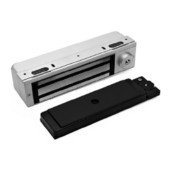
The Series 3101B-TJ101 is a 1500 pound holding force delay egress top jamb-mounted electromagnetic lock designed
to secure a single-inswinging door. The lock requires both installation procedures as described herein and in the
separate wiring instructions included.
Note: This device is not intended for use on emergency exit doors.
Typical installations of the lock on single-inswing doors:
LEFT HAND DOOR
Care must be taken that the lock face and armature face are kept free of dirt, rust, paint, or any other obstruction
which may interfere with the lock and armature making good contact. These faces may be cleaned with a non-
abrasive pad and wiped with an oil dampened cloth.
Familiarize yourself with the door and frame conditions. The lock must mount rigidly to the face of the door frame
header. The door mounted armature is supplied with an adjustable mounting bracket and hardware that allows it
to pivot slightly to compensate for reasonable misalignment.
NOTE:
If this lock is supplied with the DSM option be certain that disc magnets are present inside the
armature housing.
After mechanical installation is complete the lock needs to be wired to a 12 or 24 VDC/VAC power source. Once low
voltage power is supplied the unit is fully operational. All other wiring is for selected options. Refer to the separate
wiring instructions included for further information.
02/11
3101B-TJ101 INSTALLATION MANUAL
MODEL 3101B-TJ101
ELECTROMAGNETIC LOCK
MOUNTING INSTRUCTIONS
INSTALLATION DESCRIPTION
RIGHT HAND DOOR
HANDLING
MECHANICAL INSTALLATION
ELECTRICAL INSTALLATION
Page 1
02/11
Advertisement

Subscribe to Our Youtube Channel
Related Manuals for DynaLock 3101B-TJ101


Summary of Contents for DynaLock 3101B-TJ101
- Page 1 1-877-DynaLock www.dynalock.com INSTALLATION DESCRIPTION The Series 3101B-TJ101 is a 1500 pound holding force delay egress top jamb-mounted electromagnetic lock designed to secure a single-inswinging door. The lock requires both installation procedures as described herein and in the separate wiring instructions included.
- Page 2 FRAME RABBETT LEFT HAND DOOR RIGHT HAND DOOR 1/8” 1/8” ABOVE ABOVE HEADER RABBETT HEADER RABBETT HINGE SIDE HINGE SIDE Note: Refer to Page 6 for parts legend. Page 2 Page 7 3101B-TJ101 INSTALLATION MANUAL 02/11 3101B-TJ101 INSTALLATION MANUAL 02/11...
- Page 3 SPACER TUBE 300001 **26 5/16”-18x1” FHS TURNED 300374 *#10/32x1” TYPE F PHILIPS PAN HEAD (FOR METAL APPLICATION) ** PART OF HARDWARE PACK 301417 Refer to Page 7 for parts locations. Page 6 Page 3 3101B-TJ101 INSTALLATION MANUAL 02/11 3101B-TJ101 INSTALLATION 02/11...
- Page 4 Mount the armature and mounting bracket assembly to the door using the appropriate hardware for you door type. Firmly tighten the mounting screws with a 3/16” hex wrench. Page 4 Page 5 3101B-TJ101 INSTALLATION MANUAL 02/11 3101B-TJ101 INSTALLATION MANUAL 02/11...
Need help?
Do you have a question about the 3101B-TJ101 and is the answer not in the manual?
Questions and answers