
Related Manuals for Acconeer Entry+ XE125


Summary of Contents for Acconeer Entry+ XE125
- Page 1 Entry+ module EVK hardware user guide Entry+ module EVK hardware user guide XE125...
- Page 2 Entry+ module EVK hardware user guide Entry+ module EVK hardware user guide - XE125 Author: Acconeer Version 1.0: 2023-03-29 Acconeer AB Page 2 of 27 © 2023 by Acconeer – All rights reserved 2023-03-29...
-
Page 3: Table Of Contents
Bill of Material ......................22 3.2.3. Land Grid Array ......................22 Safety ............................. 24 4.1. Electrostatic precautions ......................24 Regulatory Information ......................... 25 Revision History ..........................26 Disclaimer ............................. 27 Page 3 of 27 2023-03-29 © 2023 by Acconeer – All rights reserved... -
Page 4: Overview Of The Xe125 Entry+ Module Evaluation Kit
The EVK consists of: 1 XE125 Evaluation board with an XM125 Entry+ module soldered onto it. The XE125 is compatible with Acconeer LH132 lens kit (LH132 is also compatible with evaluation kit XE132). LH132 is sold separately. Page 4 of 27 ©... -
Page 5: Getting Started
A Quick Installation Guide is available at https://youtu.be/Z8lQgxaJFOY This short instruction video will ensure a smooth setup and installation. As an alternative you can also find a guide in pdf-format at https://developer.acconeer.com. Page 5 of 27 2023-03-29 © 2023 by Acconeer – All rights reserved... -
Page 6: Software For The Evk
API. All APIs provided by Acconeer are documented. Unzip the SW zip file downloaded from Acconeer’s download site. In the file structure, please locate /doc folder from where API documentation in HTML format is found at doc/html/index.html. -
Page 7: The Evk Hardware
Button Button VIN_MISC Dual selection switch connector EXT/INT EXT/INT Solderbridge Power pin VIN_EXT (1.8V/3.3V) header Solderbridge Power pin header 1V8_EXT Figure 1 The block-diagram of the XE125. Page 7 of 27 2023-03-29 © 2023 by Acconeer – All rights reserved... - Page 8 Entry+ module EVK hardware user guide XM125 (32-bit, 80MHz A121 Cortex M4) BOOT0 NRST ENABLE STM32L431CBY6 INTERRUPT Flash (128kB) (64kB) 24MHz XTAL Figure 2. The block-diagram of XM125. Page 8 of 27 © 2023 by Acconeer – All rights reserved 2023-03-29...
-
Page 9: Xe125 Evaluation Board
The XE125 is powered via the USB connector J1 and/or via the pin header J8. The USB 5V power domain supplies the USB-UART chip (U2). If the USB-UART interface is not used, a dedicated USB charger can be used. Page 9 of 27 2023-03-29 © 2023 by Acconeer – All rights reserved... -
Page 10: Not Mounted Components
“No Mount”. These components are related to the FTDI I2C-USB bridge chip FT4222H which can be mounted on the PCB. It was added for internal Acconeer use. The I2C interface is also accessible in pin header J2. Refer to Table 4. -
Page 11: Electrical Schematic
Entry+ module EVK hardware user guide 3.1.4. Electrical Schematic On the following pages, please find the Electrical Schematic for XE125: Page 11 of 27 2023-03-29 © 2023 by Acconeer – All rights reserved... - Page 12 Entry+ module EVK hardware user guide Page 12 of 27 © 2023 by Acconeer – All rights reserved 2023-03-29...
- Page 13 Entry+ module EVK hardware user guide Page 13 of 27 2023-03-29 © 2023 by Acconeer – All rights reserved...
- Page 14 Entry+ module EVK hardware user guide Page 14 of 27 © 2023 by Acconeer – All rights reserved 2023-03-29...
-
Page 15: Bill Of Material
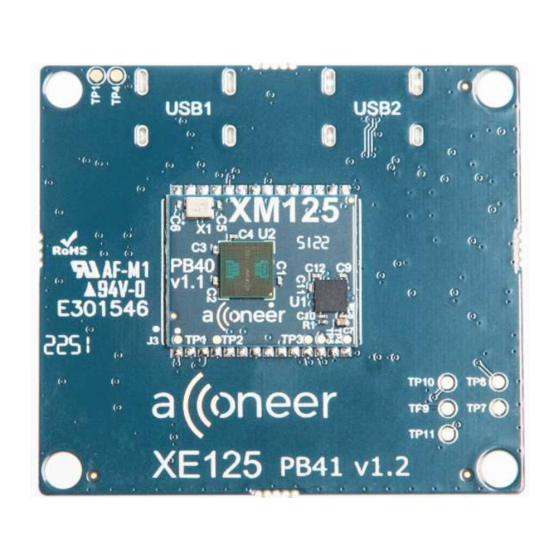
P-TR Samtec 61000821121 Wurth Electronics 3.1.6. Component Placement Drawing In Picture 3 and Picture 4 the component placement drawing of XE125, top and bottom side, are found: Page 15 of 27 2023-03-29 © 2023 by Acconeer – All rights reserved... - Page 16 Entry+ module EVK hardware user guide Picture 3. The component placement of XE125 top side. Page 16 of 27 © 2023 by Acconeer – All rights reserved 2023-03-29...
-
Page 17: Connectors
The 2x5 JTAG/SWD pin header (1.27mm pitch) contains the signals needed for flashing the XM125 MCU via the SWD interface. The pinout matches that of the Cortex 10-pin JTAG/SWD Connector and is found in Table 3. Page 17 of 27 2023-03-29 © 2023 by Acconeer – All rights reserved... - Page 18 RTS of external device. UART_RTS is connected to UART_RTS on XM125. If external UART device is connected, this pin should be connected to CTS of external device. Page 18 of 27 © 2023 by Acconeer – All rights reserved 2023-03-29...
-
Page 19: Xm125 Entry+ Module
XE125 via a Land Grid Array pattern on the bottom side of the PCB. In Picture 5 below the top and bottom side of XM125 is shown. Picture 5. The top and bottom side of XM125. Page 19 of 27 2023-03-29 © 2023 by Acconeer – All rights reserved... -
Page 20: Electrical Schematic
Entry+ module EVK hardware user guide Electrical Schematic On the following pages, please find the Electrical Schematic for XM125: Page 20 of 27 © 2023 by Acconeer – All rights reserved 2023-03-29... - Page 21 Entry+ module EVK hardware user guide Page 21 of 27 2023-03-29 © 2023 by Acconeer – All rights reserved...
-
Page 22: Bill Of Material
Table 7. XM125 LGA pinout. Pin Number Signal Comment 1.8 V or 3.3 V input A121 IO and MCU voltage Ground 1.8 V input A121 analog and digital voltage Ground Page 22 of 27 © 2023 by Acconeer – All rights reserved 2023-03-29... - Page 23 Pulling BOOT0 high during boot of module will start the embedded boot loader. Leave Not Connected if unused. Ground MCU_INT Could be used to send interrupt from MCU to host. Leave Not Connected if unused. Page 23 of 27 2023-03-29 © 2023 by Acconeer – All rights reserved...
-
Page 24: Safety
4.1. Electrostatic precautions Please take electrostatic precautions, including using ground straps, when using the EVK or any of its components. An electrostatic discharge could damage the device. Page 24 of 27 © 2023 by Acconeer – All rights reserved 2023-03-29... -
Page 25: Regulatory Information
Independent of A121 regulatory status it is the user’s responsibility to ensure that any regulatory requirements, applicable to any region, are followed in the region the device is being used. Page 25 of 27 2023-03-29 © 2023 by Acconeer – All rights reserved... -
Page 26: Revision History
Entry+ module EVK hardware user guide Revision History Date Revision Changes 2023-03-29 Original version Page 26 of 27 © 2023 by Acconeer – All rights reserved 2023-03-29... -
Page 27: Disclaimer
Entry+ module EVK hardware user guide Disclaimer The information herein is believed to be correct as of the date issued. Acconeer AB (“Acconeer”) will not be responsible for damages of any nature resulting from the use or reliance upon the information contained herein.
Need help?
Do you have a question about the Entry+ XE125 and is the answer not in the manual?
Questions and answers