
Related Manuals for Acconeer XM122


Summary of Contents for Acconeer XM122
- Page 1 IoT module EVK hardware user guide IoT module EVK hardware user guide XM122, XB122, XA122...
- Page 2 IoT module EVK hardware user guide IoT module EVK hardware user guide - XM122, XB122, XA122 Author: Acconeer Version 1.3: 2020-06-12 Acconeer AB Page 2 of 37 © 2019 by Acconeer – All rights reserved 2020-06-12...
-
Page 3: Table Of Contents
IoT module EVK hardware user guide Table of Contents Overview of the XM122/XB122/XA122 IoT Module Evaluation Kit ..........5 1.1. Introduction ..........................5 1.2. Getting Started ......................... 6 Software for the EVK ........................7 2.1. SW download .......................... 7 2.2. - Page 4 IoT module EVK hardware user guide Page 4 of 37 © 2019 by Acconeer – All rights reserved 2020-06-12...
-
Page 5: Overview Of The Xm122/Xb122/Xa122 Iot Module Evaluation Kit
Overview of the XM122/XB122/XA122 IoT Module Evaluation Kit 1.1. Introduction The XM122/XB122/XA122 IoT Module Evaluation Kit (The EVK) is a development platform that is optimized for IoT use cases where low power is important, and the device is expected to run on battery. -
Page 6: Getting Started
This short instruction video will ensure a smooth setup and installation. For more information on retrieving the Acconeer SW, please refer to the next chapter. Page 6 of 37 © 2019 by Acconeer – All rights reserved 2020-06-12... -
Page 7: Software For The Evk
API. All APIs provided by Acconeer are documented. Unzip the SW zip file downloaded from Acconeer’s download site. In the file structure, please locate /doc folder from where API documentation in HTML format is found at doc/html/index.html. -
Page 8: The Evk Hardware
& TRACE connector Selection VOUT switch VBAT connector VDD (1.8V) GPIO pin header NRST Battery Holder NRST Button Button Figure 1 The block diagram of the EVK. Page 8 of 37 © 2019 by Acconeer – All rights reserved 2020-06-12... -
Page 9: Xb122 Breakout Board
3.1. XB122 Breakout Board 3.1.1. Overview The XB122 is a breakout-board designed for the XM122 IoT Module. It makes the interfaces from the XM122 module accessible for evaluation and debug. It also enables flashing of the XM122 via USB- UART or SW-DP. The XM122 is connected to the XB122 via a board-to-board connector on the top side of the PCB. -
Page 10: Power
When the LED D1 on the XB122 is lit, the USB-UART chip is powered and ready to use. If SW1 is set to “VBUS” it also means that XM122 is powered and ready to use (if connected to the board-to- board connector on the top side of XB122). -
Page 11: Electrical Schematics
IoT module EVK hardware user guide 3.1.3. Electrical Schematics On the following pages, please find the electrical schematics for the XB122. - Page 12 IoT module EVK hardware user guide Page 12 of 37 © 2019 by Acconeer – All rights reserved 2020-06-12...
- Page 13 IoT module EVK hardware user guide Page 13 of 37 2020-06-12 © 2019 by Acconeer – All rights reserved...
-
Page 14: Bill Of Material
10 Ohm R4,R7 10/OHM/F/1005 100 kOhm R5,R6,R8,R9 100/KOHM/F/1005 SPDT Switch Manufacturer: C&K Part Number: JS102011JCQN SW2,SW3 Switch Manufacturer: C&K Part number: KMR741NG ULC LFS FT230XS-R/USB to UART bridge Page 14 of 37 2020-06-12 © 2019 Acconeer – All rights reserved... -
Page 15: Component Placement Drawing
IoT module EVK hardware user guide TPS22916BYFPR SN74LVC1G00DBVR TLV70218DBVT SSM3J133TU 3.1.5. Component Placement Drawing The component placement drawing of XB122 is found below. Top Side: Bottom Side: Page 15 of 37 2020-06-12 © 2019 by Acconeer – All rights reserved... -
Page 16: Connectors
3.1.6. Connectors USB (J1) USB is used as power supply for the XB122 and the XM122 as well as for flashing and communicating over UART. USB is connected to the FTDI chip FT230XS which converts the UART interface from XM122 into USB data signals. The pinout of J1 is shown in Table 2. - Page 17 UART_RTS 2x5 JTAG/SWD pin header (J4) The 2x5 JTAG/SWD pin header (1.27mm pitch) contains the signals needed for flashing the XM122 MCU via the SWD interface. The pinout matches that of the Cortex 10-pin JTAG/SWD Connector and is found in Table 4.
- Page 18 There are two buttons on the XB122. SW2 controls the signal “DFU” (Device Firmware Upgrade) connected to XM122 and SW3 controls “NRST” connected to the XM122. In Table 7 the state of the buttons and the corresponding signal states are listed.
-
Page 19: Xm122 Iot Module
IoT module EVK hardware user guide 3.2. XM122 IoT Module 3.2.1. Overview Picture 3 shows the XM122 IoT Module top side and Picture 4 shows the bottom side. Picture 3 Picture 4 Page 19 of 37 2020-06-12 © 2019 by Acconeer – All rights reserved... -
Page 20: Electrical Schematics
IoT module EVK hardware user guide 3.2.2. Electrical Schematics Please find the electrical schematics of the XM122 below. Page 20 of 37 2020-06-12 © 2019 Acconeer – All rights reserved... - Page 21 IoT module EVK hardware user guide Page 21 of 37 2020-06-12 © 2019 by Acconeer – All rights reserved...
- Page 22 IoT module EVK hardware user guide Page 22 of 37 © 2019 by Acconeer – All rights reserved 2020-06-12...
- Page 23 IoT module EVK hardware user guide Page 23 of 37 2020-06-12 © 2019 by Acconeer – All rights reserved...
-
Page 24: Bill Of Material
IoT module EVK hardware user guide 3.2.3. Bill of Material Table 8 shows the BOM for the XM122. Table 8 The BOM for XM122 Component Ref. Specification QTY Value Comment C2,C7,C18,C22,C25,C 100/NF/K/50V/X7R/1005 100 nF 29,C31,C32 C3,C5,C27,C28,C30,C 1/UF/K/10V/X5R/1005 47/NF/K/50V/X5R/1005 47nF C8,C9... - Page 25 33 Ohm 0.5/OHM/J/1005 0.5 Ohm R8,R13 0/OHM/J/1005 0 Ohm 470/KOHM/F/1005 470 kOhm U1,U4 TPS22916BYFPR NORDIC_BT5.0_LONGRANG E_NRF52840 TPS62840DLCR A111 R2D BU4818F-TR 32MHz/10ppm/10PF/50OH M/2520 32.768kHz/20ppm/9.5PF/9 0KOHM/2 TSX-3225 24.0000MF20G- AC0/SMD Page 25 of 37 2020-06-12 © 2019 by Acconeer – All rights reserved...
-
Page 26: Component Placement Drawing
IoT module EVK hardware user guide 3.2.4. Component Placement Drawing The component placement drawing of XM122 is found below. Top side: Bottom side: Page 26 of 37 © 2019 by Acconeer – All rights reserved 2020-06-12... -
Page 27: Pinning
IoT module EVK hardware user guide 3.2.5. Pinning Table 9 shows the pinout of the XM122 connector J2. Table 9 The pinout of the XM122 connector J2. Pin Number Signal Pin Number Signal GPIO P0.23 VOUT GPIO P0.21 VOUT GPIO P0.24 GPIO P0.04... -
Page 28: Using The Iot Module Without The Breakout Board
The IoT module can be used without connecting it to the board-to-board connector if external power is supplied. In this way the XM122 can operate as a standalone module or connected to other hardware. In XM122 R2D a NOT MOUNTED battery connector has been added to the design. For XM122 R2C, power supply leads or connection to a battery can be soldered onto the pads of C38 (not mounted), see Error! Reference source not found.. -
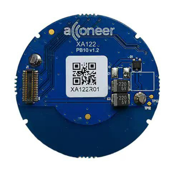
Page 29: Xa122 Battery Board
CR2477 battery holder (battery NOT included), tantalum capacitors for handling current peaks from the XM122 IoT module and a switch preventing the battery from being short-circuited if inserted incorrectly. It also enables access to some of the interfaces in the board-to- board connector via test points. -
Page 30: Electrical Schematics
IoT module EVK hardware user guide 3.3.2. Electrical Schematics The electrical schematics for the XA122 is found below: Page 30 of 37 2020-06-12 © 2019 Acconeer – All rights reserved... -
Page 31: Bill Of Material
Part number: 3039 DF40C-30DP-0.4V51 Manufacturer: Hirose SSM3J133TU Manufacturer: Toshiba 3.3.4. Component Placement Drawing The component placement drawing of XA122 is found below. Top Side: Bottom Side: Page 31 of 37 Proprietary and Confidential © 2019 by Acconeer – All rights reserved 2020-06-12... -
Page 32: Connectors
IoT module EVK hardware user guide 3.3.5. Connectors 3.4. Connectors 30 pin board-to-board connector (J1) The 30-pin board-to-board connector is intended to connect the XM122 to the XA122. The pinout is found in Table 3. Table 11. The pinout of J1. Pin Number... -
Page 33: Test Points
UART_RTS 3.5. Test Points XA122 has 11 test points which makes signals from the XM122 IoT Module available for probing or external connection. The test points on the bottom side of XA122 are listed in Table 12. Table 12 The test points on XA122... -
Page 34: Safety
Please take electrostatic precautions, including using ground straps, when using the EVK or any of its components. An electrostatic discharge could damage the device. Page 34 of 37 Proprietary and Confidential © 2019 by Acconeer – All rights reserved 2020-06-12... -
Page 35: Regulatory Information
EU - Electromagnetic Compatibility Directive: Not Performed South Korea – Kc, Korea certification: Not Performed Independent of XM122 regulatory status it is the user’s responsibility to ensure that any regulatory requirements, applicable to any region, are followed in the region the device is being used. -
Page 36: Revision History
Updated Table 9 with correct signal names. Updated chapter 3.1.3, “Electrical Schematics” with correct net names for UART signals. 2020-06-12 Added chapter 3.3 XA122 Battery Board Page 36 of 37 Proprietary and Confidential © 2019 by Acconeer – All rights reserved 2020-06-12... -
Page 37: Disclaimer
IoT module EVK hardware user guide Disclaimer The information herein is believed to be correct as of the date issued. Acconeer AB (“Acconeer”) will not be responsible for damages of any nature resulting from the use or reliance upon the information contained herein.
Need help?
Do you have a question about the XM122 and is the answer not in the manual?
Questions and answers