Table of Contents
Advertisement
Advertisement
Table of Contents

Subscribe to Our Youtube Channel
Related Manuals for VINKA DR23


Summary of Contents for VINKA DR23
- Page 1 DR23 The ebike Display User Manual...
-
Page 2: Table Of Contents
Contents Product name and model............................1 Specifications................................1 Appearance and dimension..........................1 Function and button definition..........................1 ◆Function summary.............................. 2 ◆Function layout..............................2 ◆Button definition..............................2 Installation................................3 General operations..............................3 ◆Switch E-bike system ON/OFF.........................3 ◆Display interface..............................3 ◆Push-assistance ..............................3 ◆Switch lighting ON/OFF............................. 4 ◆Assist level selection............................ -
Page 3: Product Name And Model
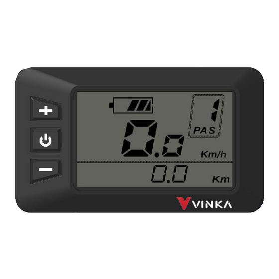
Product appearance and dimensional drawing (unit: mm) *Display side is cable free. Function and Button Definition ◆Function Summary DR23 has many functions to meet riders’ needs. The indication elements are as follows: ●Intelligent battery SOC indication ●Motor output power indication ●Assist level selection and indication ●Speed indication (incl. -
Page 4: Function Layout
-/push assist Installation DR23 can be mounted on the left side of handlebar close to its grip. Adjust the angle for a good screen view. Cut off the power before connecting the corresponding connectors between display and controller. General Operation... -
Page 5: Switch E-Bike System On/Off
◆Switching the E-bike System mode ON/OFF To switch on the E-bike system and provide the power supply to the controller, hold the On/Off button for 1s. To switch off E-bike system, hold the On/Off button for 1s. The E-bike system no longer uses the battery power. -
Page 6: Switch Lighting On/Off
Push-assistance mode ■The power-assisted push function can only be used when the user pushes the electric vehicle, please do not use it in the riding state ◆Switching Lighting ON/OFF Long press the UP button for more than 1 second to turn on the headlights, the instrument display shows the headlight symbol, and the brightness of the display backlight decreases. -
Page 7: Battery Indicator
◆Battery Indicator The five battery power bars represent the capacity of the battery. The five battery bars are bright when the battery is in full voltage. When the battery is in low voltage, battery frame will flash at the frequency of 1HZ to give a notice that the battery needs to be recharged immediately Flash (low voltage) Battery Indicator... -
Page 8: Controller Software Version
◆Controller software version CLS refers to controller software version number. The version number is reported by the controller. It can not be adjusted from display side Controller version number reading interface ◆display software version DPS refers to display software version number. The display software version is not adjustable. It is decided by the software. -
Page 9: Brightness
◆Brightness bLG refers to Backlight level settings. The settable range is 1 2 3 4 5. 1 is the darkest, 3 is standard and 5 is the brightest. The default value is decided by the controller when the display leaves factory. Press UP/DOWN to change the brightness levels. -
Page 10: Trip Clear Function
◆TRIP clear function In TRIP mode and Trip is not 0, press the UP and DOWN buttons at the same time for more than 1 second to clear the trip data information. ◆Exit settings In personalized parameter settings interface, Short press the ON/OFF button is to confirm the input. Hold the ON/OFF button is to store the settings and exit the current setting. -
Page 11: Warnings
3. Don’t modify system parameters to avoid parameter disorder. 4. Make the display repaired when error code appears. ■ This manual instruction is a universal version for VINKA DR23 display. Software specific, versions of this display may be different. Please always refer to version. -
Page 12: Attached List 1:Error Code Definitions
Attached list 1: Error code definition Error code Definition Torque Zero Error Torque Out Range Torque Sensor Fault Gear Sensor Error Speed Sensor Error Cadence Error PCB Over-Temp Warning PCB Over-Temp Error PCB Sensor Fault Motor Over-Temp Warning Motor Over-Temp Error Flash Error Communication Lost LORA Communication Lost... -
Page 13: Attached List 2:Functions Corresponding To Instrument Characters
Attached list 2:Functions corresponding to instrument characters Symbol Definition Wheel diameter Controller software version Display software version Unit exchange Backlight level Speed limit Push assistant speed...
Need help?
Do you have a question about the DR23 and is the answer not in the manual?
Questions and answers
Is the VINKA supplied with the VALK Cyclone 7 + in Australia different to other countries, the Manual Supplied has a different layout to the actual Vinka supplied and far less options, is it possible to replace the one i have with the one in this manual?