Table of Contents

Related Manuals for Franklin Water Treatment SWS1 Series

Summary of Contents for Franklin Water Treatment SWS1 Series
- Page 1 Installation Instructions and Owner’s Manual SWS1 Series Water Softening System Franklin Water Treatment, LLC. 12630 US Highway 33 N Churubusco, IN 46723 Phone (260) 693-1972 Fax (260) 693-0602 SWS1 Series Instruction Manual 230123AF.docx...
-
Page 2: Table Of Contents
Table of Contents Pre-installation Instructions Page 3 Detailed Installation Page 5 Brine Tank Components Page 6 Bypass Valve Operation Page 7 General Operation & Set Time of Day Page 8 Installer Settings & Regeneration Display Page 9 Manual Regeneration Page 10 Specifications Page 11 Component Parts Breakdown &... - Page 3 This page intentionally left blank...
-
Page 4: Pre-Installation Instructions
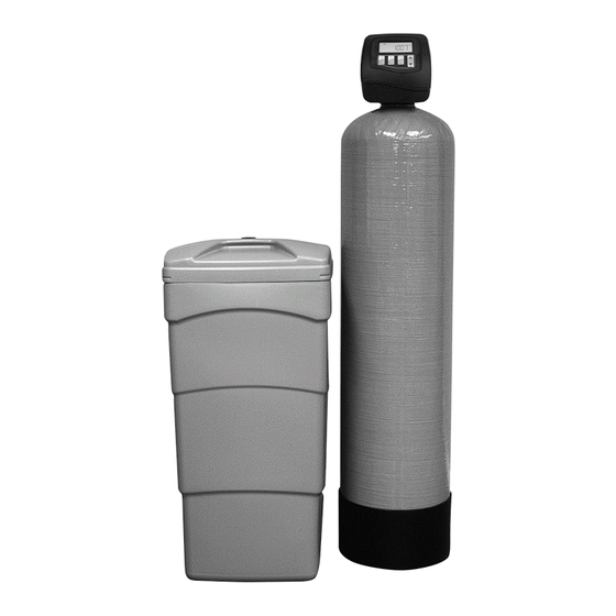
Pre-installation Instructions Description of the water softener system This water softener system includes a brine (salt) tank and a resin (media) tank with a backwashing control valve. Incoming water flows into the control valve and is directed down through the ion exchange softening resin. - Page 5 Pre-installation Instructions (cont.) Location Considerations The proper location to install the water softener system will ensure optimum performance and satisfactory water quality. The following factors should be considered in selecting the location of the equipment. 1. The water softener should be installed after the pressure tank on a private well system or after the water meter on municipal water.
-
Page 6: Detailed Installation
Detailed Installation Instructions STEP 1: Carefully remove all components from packaging. DO NOT DISCARD PACKAGING until all water softener components and fittings have been located. STEP 2: Using the integrated coupling nuts, attach the bypass valve to the inlet/outlet of the control valve and put handles in the bypass position (Figure 2) STEP 3: Place unit at desired installation position. -
Page 7: Brine Tank Components
Detailed Installation Instructions (continued) Connect one end of the 3/8” brine line to the control valve quick connect brine refill elbow STEP 7: (Figure 2, Page 5). Insert the other end of the brine line through the hole in the brine tank and into the quick connect fitting on the top of the safety brine valve (Figure 3). -
Page 8: Bypass Valve Operation
Detailed Installation Instructions (continued) FIGURE 4: Bypass Valve Operation With the bypass valve in the “Bypass” position (refer to Figure 2, Page 5; Figure 4, Page 7), STEP 12: press and hold the REGEN button until the motor starts. Then use the REGEN button to advance the control valve to the BACKWASH cycle (refer to page 10 for details) to release pressure and purge air from the mineral tank. -
Page 9: General Operation & Set Time Of Day
General Operation When the system is operating one of two displays will be shown. Pressing NEXT will alternate between the displays. One of the displays is always the current time of day. The second display is gallons remaining. This is the number of gallons that can be treated before the system needs to go through a regeneration cycle. -
Page 10: Installer Settings & Regeneration Display
Installer Settings Step 1 - Press NEXT and ▲ simultaneously for 3 seconds. Step 2 - Hardness: Set the amount of adjusted hardness in grains per gallon (hardness gpg + (iron ppm x 3) + (manganese ppm x 5)) using ▲ or ▼ buttons. The default is 20 with value ranges from 1 to 150 in 1 grain increments. -
Page 11: Manual Regeneration
Manual Regeneration Sometimes there is a need to regenerate the system, sooner than when the system calls for it, usually referred to as manual regeneration. There may be a period of heavy water usage because of guests or a heavy laundry day. -
Page 12: Specifications
Specifications Space Two Tank Models Cabinet Models Saver Description Model SWS1-0948 SWS1-1054 SWS1-1248 SWS1-1354 SCCWS1-1035 SCCWS1-1044 SWS1C-1035 Resin Volume ft Capacity, grains @Factory Salt 24,000 36,000 48,000 60,000 24,000 32,000 24,000 @Max. Salt @ 15lb/ft 30,000 45,000 60,000 75,000 30,000 39,000 30,000 Gravel Underbed, lbs... -
Page 13: Component Parts Breakdown & List
Component Parts Breakdown Cabinet Models Space Saver Two Tank Models Cabinet Model Model Description SWS1-0948 SWS1-1054 SWS1-1248 SWS1-1354 SCCWS1-1035 SCCWS1-1044 SWS1C-1035 Control Valve SWS1-0948-VLV- SWS1-1054-VLV- SWS1-1248-VLV- SWS1-1354-VLV- SWS1C-1035- SCCWS1-1035- SCCWS1-1044- L/ bypass ASSY- L-BP ASSY- L-BP ASSY- L-BP ASSY- L-BP VLV-ASSY-L-BP VLV-ASSY-L-BP VLV-ASSY-L-BP... -
Page 14: Control Valve Exploded Parts Diagram
Control Valve Breakdown... -
Page 15: Control Valve Parts List
Control Valve Parts List REF # Part Number Description CV3002SWS1 Drive Assembly, SWS1 Series CV3186-06 Power Cord with Transformer, 15 VDC CV3003 Meter and Cable Assembly CV3006 Bypass Valve, Less Fittings CV3992-01 Front Cover, Black, SWS Series CV3107-01 Drive Motor... -
Page 16: Installation Fitting Assemblies
Installation Fitting Assemblies 3/4" & 1" PVC SOLVENT ELBOW 1" PVC MALE NPT ELBOW Part # Description Part # Description 3/4" & 1" PVC solvent CV3007-01 1" PVC male NPT CV3007 elbow assy elbow assy CV3151 Nut, 1" quick connect CV3151 Nut, 1"... - Page 17 Installation Fitting Assemblies (cont.) 1" BRASS SHARK BITE 3/4" BRASS SHARK BITE Part # Description Part # Description 1" brass shark bite CV3007-13 3/4" brass shark bite CV3007-12 assembly assembly CV3151 Nut, 1" quick connect CV3151 Nut, 1" quick connect CV3150 Split ring CV3150...
- Page 18 Installation Fitting Assemblies (cont.) 3/4" QUICK CONNECT Description Part # 3/4" QUICK CONNECT QFNCR4 (*2 required) SERVICE WRENCH - CV3193 Although no tools are necessary to assemble or disassemble the valve, the Service Wrench, (shown in various positions on the valve) is available to aid in assembly or disassembly.
-
Page 19: Troubleshooting
Troubleshooting PROBLEM CAUSES SOLUTIONS A) Loose nut at either end of the brine line B) Brine line inserted into the brine tank 1) Tighten nuts at either end of brine line overflow fitting 2) Verify brine line is installed correctly rather than 3) Verify softener drain line is not connected connected to the... - Page 20 Troubleshooting (cont.) PROBLEM CAUSES SOLUTIONS A) Clock is not set 1) Reset softener clock (page 8) Softener regenerates B) Power outage 2) Verify control valve programming (pages 9 at wrong time of day C) Incorrect control & 11) valve programming A) Unit is installed 1) Re-plumb unit with water supply entering Resin in water lines,...
- Page 21 E) Defective PC board 5) Replace PC board if needed Troubleshooting (cont.) PROBLEM CAUSES SOLUTIONS A) Outlet is on a switch Display shows B) Power outage 1) Use an un-switched outlet incorrect time-of-day C) Control valve was 2) Reset time-of-day or time-of-day flashes reset 3) Replace circuit board if needed...
-
Page 22: Ten Year Limited Warranty
TEN YEAR LIMITED WARRANTY WARRANTY – Franklin Water Treatment, LLC, warrants this water conditioner against any defects that are due to faulty material or workmanship during the warranty period. This warranty does not include damage to the product resulting from accident, neglect, misuse, misapplication, alteration, installation, or operation contrary to printed instructions, or damage caused by freezing, fire, flood, or Acts of God.
Need help?
Do you have a question about the SWS1 Series and is the answer not in the manual?
Questions and answers