Table of Contents
Advertisement
OWNERS GUIDE TO INSTALLATION
Read these installation instructions in detail before installing your pump. Be sure to check the
following:
1. Be certain the motor is connected for the correct line voltage being used (check motor
nameplate).
2. Be certain the pump is completely primed before starting. Otherwise damage may occur to the
seal.
Every pump is tested before leaving the factory, and its performance depends largely on the
installation.
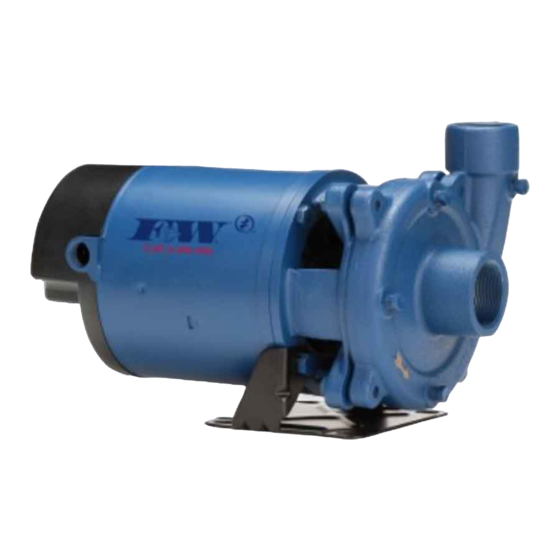
Figure 1 - CJ103 Series
GENERAL SAFETY INFORMATION
1. Follow all local electrical and safety codes, as
well as the National Electrical Code (NEC) and
the Occupational Safety and Health Act (OSHA).
2. Replace damaged or worn wiring cord
immediately.
3. Do not kink power cable and never allow the
cable to come in contact with oil, grease, hot
surfaces or chemicals.
4. Protect the power cable from coming in contact
with sharp objects.
5. Be careful when touching the exterior of an
operating motor - it may be hot enough to be
painful or cause injury.
6. Make certain that the power source conforms
to the requirements of your equipment.
7. Always disconnect power source before
performing any work on or near the motor or
its connected load. If the power disconnect
point is out-of-sight, lock it in the open position
and tag it to prevent unexpected application
of power. Failure to do so could result in fatal
electrical shock.
95 North Oak Street • Kendallville, IN 46755 • Copyright © 2010. All rights reserved.
AND OPERATION
READ THESE INSTRUCTIONS CAREFULLY
END SUCTION CENTRIFUGAL PUMPS
IL0412
Figure 2 - CJ101 Series
8. Do not handle the pump with wet hands or
when standing in water as fatal electrical shock
could occur. Disconnect main power before
handling unit for ANY REASON!
9. Unit must be securely and adequately
electrically grounded. This can be
accomplished by wiring the unit to a ground
metal-clad raceway system or by using a
separate ground wire connected to the bare
metal of the motor frame or other suitable
means.
10.
pump has not been investigated for use in
swimming pool areas.
11.
chemicals known to the State of California
to cause cancer and birth defects or other
reproductive harm.
NOTE: Pumps with the "CSA" mark are tested to
UL standard UL778 and certified to CSA standard
C22.2 No. 108.
1
FW0078
Supersedes
IL0201
Drain Plug
Risk of electric shock. This
This product contains
130441
0811
0310
Advertisement
Table of Contents

Subscribe to Our Youtube Channel
Related Manuals for Flint & Walling CJ103 Series


Summary of Contents for Flint & Walling CJ103 Series
- Page 1 END SUCTION CENTRIFUGAL PUMPS IL0201 Drain Plug IL0412 Figure 1 - CJ103 Series Figure 2 - CJ101 Series GENERAL SAFETY INFORMATION 8. Do not handle the pump with wet hands or when standing in water as fatal electrical shock 1.
-
Page 2: Motor Data
Dimensions (In Inches) CJ103 Series Chart A 4-5/8 3-11/16 4-13/16 9-3/16 2-1/2 8-1/4 8-1/8 13-1/4 3-7/8 4-5/8 3-11/16 4-13/16 9-3/16 2-1/8 8-1/4 8-1/8 13-1/2 3-7/8 4-5/8 3-11/16 4-13/16 9-3/16 2-1/8 8-1/4 8-1/8 3-7/8 4-5/8 3-11/16 4-13/16 9-3/16 2-1/8 8-1/4 8-1/8... -
Page 3: Typical Installations
Typical Installations To size pressure tank properly, match the Union Check Valve drawdown of the tank Main Power Box to the capacity of the Street Supply pump. (*) For manual Gate/Ball Valve Gate/Ball Valve operation, omit the (Normally Open) (Normally Open) pressure tank and Pressure pressure switch. -
Page 4: Pump Performance
When unpacking the unit, inspect carefully for any damage that may have occurred during shipment. 5. CJ103 Series pumps incorporate a discharge If the unit is received sometime before it can be port on the pump casing that can be adjusted used, it should be inspected, recrated and stored in 90 increments. -
Page 5: Pump Installation
Practical Suction Lifts at Various Elevations and Pressure Gauge Water Temperatures in Degrees Fahrenheit Priming Plug Discharge Tee Altitude 60º 80º 100º 120º 140º 160º 180º 200º Sea Level -22 Suction Pipe Installed with 2000 Gradual Rise to Pump Inlet 4000 6000 8000... -
Page 6: Motor Protection
ELECTRICAL nameplate or figures 8, 9 & 10. Replace rear access cover before Ground motor before connecting starting or operating pump. Failure to do so can result to electrical power supply. in personal injury. MOTOR PROTECTION Connect the motor frame to 1. -
Page 7: Motor Rotation
line, pump casing, and discharge line up to the level of supply. Fused 3. Where the pump is operating with suction Disconnect Switch lift and the suction line is equipped with a foot valve, remove the priming plug from the discharge tee (see Figures 5-8) and fill the Lightning pump body and suction pipe completely with... -
Page 8: Maintenance
MAINTENANCE counterclockwise. Remove the intermediate stage (stages) taking care not to damage the Lubrication gasket (gaskets) and unthread the remaining The pumps and motors require no lubrication. impellers. The ball bearings of the motor have been greased 4. Remove the mechanical seal assembly. The at the factory. -
Page 9: Troubleshooting Chart
2. Follow steps as outlined under Rotary Seal connected at the bottom of the mounting frame Replacement to remove the pump body, with two (2) 3/8” x 1/2” cap screws. diffuser, impeller and rotary seal. 5. Follow steps of Rotary Seal Assembly to 3. - Page 10 FORM NO. FW0039 0110 SUPERSEDES 1009 PAGE 4-1A REPAIR PARTS CENTRIFUGAL PUMP REPAIR PARTS “CJ103” SERIES (For Pricing Refer To Repair Parts Price List) IL0417 1-1/2 STAGE SINGLE PHASE CJ103031 CJ103051 CJ103071 CJ103101 CJ103151 CJ103201 BRASS IMPELLER THREE PHASE CJ103053 CJ103073 CJ103103 CJ103153...
- Page 11 FORM NO. FW0040 0811 SUPERSEDES 0310 CENTRIFUGAL PUMP REPAIR PARTS “CJ101” SERIES (For Pricing Refer To Repair Parts Price List) Detail of Intermediate Stage Assembly Square Cut Ring 1-1/2 STAGE ITEM SINGLE PHASE - BRASS IMPELLER CJ101B071 CJ101B101 CJ101B151 CJ101B201 CJ101C201 CJ101C301 CJ101B073 CJ101B103 CJ101B153 CJ101B203 CJ101C203 CJ101C303...
Need help?
Do you have a question about the CJ103 Series and is the answer not in the manual?
Questions and answers