Advertisement
SAFETY INFORMATION
Please read and understand this entire manual before attempting to assemble, operate or install the
product. If you have any questions regarding the product, please call customer service at
1-800-742-5044, 7:30 a.m.-5:00 p.m., EST, Monday-Friday.
DANGER
ELECTRICAL SHOCK HAZARD.
Always disconnect power source before performing
any work on or near the motor or its connected load.
If the power disconnect point is out-of-sight, lock it in
the open position and tag it to prevent unexpected
application of power. Failure to do so could result in
fatal electrical shock.
ELECTRICAL SHOCK HAZARD.
Do not handle the pump with wet hands or when
standing in water as fatal electrical shock could occur.
Disconnect main power before handling unit for ANY
REASON!
RISK OF ELECTRIC SHOCK.
These pumps have not been investigated for use in
swimming pool areas.
WARNING
ELECTRICAL SHOCK ALERT.
Follow all local electrical and safety codes, as well
as the National Electrical Code (NEC) and the
Occupational Safety and Health Act (OSHA).
ELECTRICAL SHOCK ALERT.
Replace damaged or worn wiring cord immediately.
ELECTRICAL SHOCK ALERT.
Do not kink power cable and never allow the cable
to come in contact with oil, grease, hot surfaces, or
chemicals.
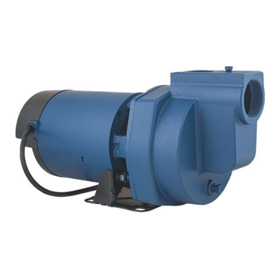
LAWN SPRINKLER,
IRRIGATION PUMP
MODEL #, SP10P1, SP15P1, SP20P1,
ELECTRICAL SHOCK ALERT.
Unit must be securely and adequately electrically
grounded. This can be accomplished by wiring the unit
to a ground metal-clad raceway system or by using a
separate ground wire connected to the bare metal of
the motor frame or other suitable means.
CHEMICAL ALERT.
This product contains chemicals known to the State of
California to cause cancer and birth defects or other
reproductive harm.
CAUTION
ELECTRICAL SHOCK MAY OCCUR
Protect the power cable from coming in contact with
sharp objects.
HOT SURFACE MAY CAUSE BURNS
Be careful when touching the exterior of an operating
motor - It may be hot enough to be painful or cause
injury.
PRODUCT DAMAGE MAY RESULT
Make certain that the power source conforms to the
requirements of your equipment.
EL10P1, EL15P1, EL20P1
023264 G
Advertisement
Table of Contents

Related Manuals for Flint & Walling SP10P1


Summary of Contents for Flint & Walling SP10P1
- Page 1 LAWN SPRINKLER, IRRIGATION PUMP MODEL #, SP10P1, SP15P1, SP20P1, EL10P1, EL15P1, EL20P1 SAFETY INFORMATION Please read and understand this entire manual before attempting to assemble, operate or install the product. If you have any questions regarding the product, please call customer service at 1-800-742-5044, 7:30 a.m.-5:00 p.m., EST, Monday-Friday.
- Page 2 PREPARATION Before beginning installation of product, make the product. Contact customer service for sure all parts are present. Compare parts replacement parts. with package contents drawing. If any part is missing or damaged, do not attempt to assemble Estimated Installation Time: 2 hours. Tools Required for Assembly: 2-step PVC glue system (primer and sealer) Hacksaw...
-
Page 3: General Pump Information
GENERAL PUMP INFORMATION Typical Pump Setup Fig 1 Fig 2 Typical setups for lawn sprinkler pump systems 60 ft. max. include ground water wells (Fig. 1) or surface Outlet Inlet pipe to water Pipe water, such as lakes, ponds or streams. (Fig. 3) Pipe Support Vertical... - Page 4 PUMP PREPARATION FOR WELL AND SURFACE WATER Fig 1 Fig 2 CAUTION: Dry-fit entire assembly to ensure proper fit before gluing or taping parts. CAUTION: Follow all proper gluing procedures as specified by the glue manufacturer. Always glue in a vertical direction whenever possible to prevent glue from dripping inside pipe or fittings IL1252...
- Page 5 PUMP PREPARATION FOR WELL AND SURFACE WATER For Well Installations Fig 11 Fig 12 11. Thread a 2 in. MPT x 2 in. slip adaptor into the foot valve. 12. Glue 2 in. pipe into the adaptor. Glue enough sections of pipe together using 2 in. couplers in order for the foot valve to be completely submerged in water.
- Page 6 PUMP INSTALLATION FOR WELL AND SURFACE WATER 1. Mount pump on a solid foundation as close to Fig 1 Fig 2 the water source as possible. Priming Plug 100 PSI Ball Pressure Union Valve Gauge Outlet Pipe 2 in. CAUTION: Support the 2 in. inlet Female Union Outlet...
- Page 7 PUMP ELECTRICAL INSTRUCTIONS WARNING WIRE SIZE CHART ELECTRICAL SHOCK ALERT. Minimum Copper Wire Size Chart (Gauge) Distance From Under-size wiring can cause motor failure and Single Phase Motors Motor To Fuse even fire. Use proper wire size specified in the 1 HP 1-1/2 HP 2 HP...
- Page 8 PUMP ELECTRICAL CONNECTIONS 1. Remove rear motor cover on pump by Fig 1 Fig 2 unscrewing the two screws. 2. Thread electric wire strain relief into wire opening on the side of the motor of pump. 3. Insert wire through electric wire strain relief and tighten screws.
- Page 9 PUMP PRIMING & STARTUP Fig 1 Fig 2 CAUTION: All pumps must be primed by Priming Plug with filling the pump cavity with water before they Outlet Pipe Pressure Gauge Priming Plug are first operated. This may take several gallons with Pressure Gauge of water, as the entire inlet line will be filled in...
-
Page 10: Maintenance
MAINTENANCE LUBRICATION Fig 1 The pump and motor requires no lubrication. The ball bearings of the motor have been greased at the factory. Under normal operating conditions they should require no further greasing. Remove ROTARY SEAL ASSEMBLY REPLACEMENT Mechanical CAUTION: Make certain that the power Seal supply is disconnected before attempting to service the unit. -
Page 11: Troubleshooting
TROUBLESHOOTING Problem Possible Cause Corrective Action A. Little or no 1. Casing not initially filled with water 1. Fill pump casing discharge 2. Vertical lift too high, or too long 2. Move pump closer to water source 3. Hole or air leak in inlet line 3. -
Page 12: Replacement Parts List
REPLACEMENT PARTS LIST To order parts, call 1-800-742-5044 Motor Assembly 1-1/2 SINGLE PHASE MODEL NO. SP10P1 SP15P1 SP20P1 ITEM DESCRIPTION PART NO. Ring, Square Cut 132429 Seal, Rotary and Ceramic (with 131100 Spring) Impeller 023211 134138 134138 Diffuser 132425 Diffuser Insert...
Need help?
Do you have a question about the SP10P1 and is the answer not in the manual?
Questions and answers