Table of Contents
Advertisement
Available languages
Available languages
Quick Links
1/3 - 1/2 HP "CPJS"
SHALLOW WELL
1/2 HP "CPJ"
CONVERTIBLE
Top
Shallow Well Ejector for lifts to 25
ft.
STOP
Monday thru Friday - 7:30 am to 5:00 pm EST
Installation Instructions and Parts Manual
"CPJ" SERIES JET PUMPS
Shallow Well Jet Pumps
IL0189
Convertible Jet Pumps
IL0192
Ejectors (Purchase separately)
TOP
Convertible Ejector For Shallow
or Deep well applications (4 inch
inside diameter wells).
For loose, missing or damaged parts, or if the
unit does not seem to be operating properly,
please call before returning unit to the place of
purchase
Phone: 1-800-742-5044
Service Hours:
3/4 - 1-1/2 HP "CPJS"
SHALLOW WELL
3/4 - 1-1/2 HP "CPJ"
CONVERTIBLE
Top, if used for
shallow well
IL0194
IL0195
Single Pipe Deep Well
Ejector (2 inch inside
diameter wells).
132463 E
IL0188
Advertisement
Table of Contents

Related Manuals for Flint & Walling CPJ Series


Summary of Contents for Flint & Walling CPJ Series
- Page 1 Installation Instructions and Parts Manual “CPJ” SERIES JET PUMPS Shallow Well Jet Pumps 1/3 - 1/2 HP “CPJS” 3/4 - 1-1/2 HP “CPJS” SHALLOW WELL SHALLOW WELL IL0189 Convertible Jet Pumps 1/2 HP “CPJ” 3/4 - 1-1/2 HP “CPJ” IL0188 CONVERTIBLE IL0192 CONVERTIBLE...
-
Page 2: Safety Information
SAFETY INFORMATION 6. This product contains chemicals known to the State of DANGER: California to cause cancer and birth defects or other 1. Always disconnect power source before performing any reproductive harm. work on or near the motor or its connected load. If the 7. -
Page 3: General Pump Information
GENERAL PUMP INFORMATION Typical Pump Setup 3/4 or 1 in. Convertible jet pumps are designed for use in these Discharge Pipe applications: Discharge to Home 1. Shallow wells (0 - 25 ft. lift) where ejector bolts to pump Suction (Fig. 1) Lift 1-1/4 in. - Page 4 GENERAL PUMP INFORMATION 3. Deep wells where well ID is 2” or more and a single Discharge pipe (packer) ejector is installed in the well. (Fig. 3) to Home 3/4 or 1 in. Discharge Suction Pipe Pipe See Table B Pipe Support 2 in.
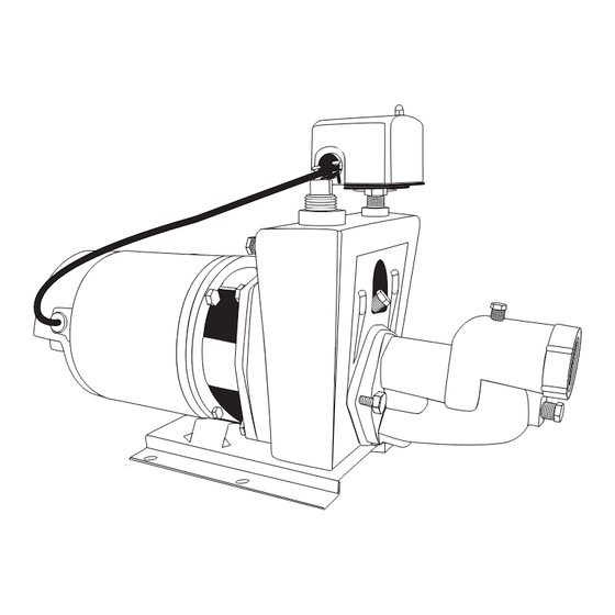
- Page 5 GENERAL PUMP INFORMATION 6. CPJ Shallow Well 1/3 - 1/2 HP (Fig. 6) Pressure Switch Priming Port Discharge Suction Shallow Well Ejector IL0189 Ventilation WIRE SIZE CHART CHART 2 Ventilation and drainage must be provided to prevent Recommended Copper Wire and Fuse Sizes damage to the motor from heat and moisture.
- Page 6 PREPARATION Before beginning installation of product, make sure all parts are present. If any part is missing or damaged, do not attempt to assemble the product. Contact customer service for replacement parts. Estimated Installation Time: 2 hours. Tools required Pipe wrenches (2) Wire cutters Wire strippers Adjustable wrench...
- Page 7 INSTALLING PIPING IN WELL When connecting a drive point (Fig. 2) a check valve must 3/4 or 1 in. be used in the suction line in place of a foot valve. For easy Discharge Pipe priming connect the check valve as close to the well as Discharge possible.
- Page 8 INSTALLING PIPING IN WELL Deep Well (Single Pipe System) Discharge Application - Where pumping water level is greater than 25 to Home feet and inside diameter of well is 2, 2-1/2 or 3 inches. (Fig 3/4 or 1 in. Discharge Suction On single pipe deep well installations, clean, sound well Pipe...
- Page 9 WELL TO PUMP CONNECTION (SUCTION PIPE) 1. Attach ejector to face of pump with two (2) bolts and gasket provided. Venturi tube on the ejector inserts into Priming Port This Side Ejector the top tapping of the face of the pump (Fig. 1). Venturi Tube 2.
- Page 10 WELL TO PUMP CONNECTION (SUCTION PIPE) 4b. For driven wells, a check valve is required at the top of the well to maintain prime. Flow arrow must point toward pump. (Fig. 4b) Flow Arrow Pump IL1475 5. Finish the connection to your well with additional pipe and fittings as needed.
- Page 11 PUMP TO PRESSURE TANK CONNECTION (DISCHARGE PIPE) Shallow Well Application Only: 1. Begin the connection to the pressure tank. Using a 3/4 in. x 3 in. galvanized nipple, wrap the threads 5 times with pipe tape and apply pipe paste (pipe dope) and install in top of pump.
- Page 12 PUMP TO PRESSURE TANK CONNECTION (DISCHARGE PIPE) Deep Well Application Only: 1. To begin the connection to the pressure tank, loosely Flow assemble flow control body to pump head. Using Control Teflon tape, position the discharge outlet of the control Control Screw body facing right as you look directly into the face of...
- Page 13 PUMP TO PRESSURE TANK CONNECTION (DISCHARGE PIPE) 5. Continue with fittings and pipe to the pressure tank. A 3/4 in. union is optional but recommended for easy connection and disconnection. (Fig. 5) CAUTION: Install a pressure relief valve on any installation where the pump pressure can exceed the maximum working pressure of the tank.
-
Page 14: Shut Off Valve
TANK TO HOUSE CONNECTION 3. Attach a 1 in. slip (glue) x 3/4 in. FPT adapter and Coupling 3/4 in. MPT x 3/4 in. slip. (Fig. 3) Adapter Glue 4. Install a 3/4 in. union (optional) and continue with pipe and 3/4 in. x 3/4 in. x 3/4 in. tee. (Fig. 4) Glue Union IL1368... -
Page 15: Wiring Diagram
PUMP ELECTRICAL CONNECTIONS WIRING DIAGRAM CAUTION: All wiring should be performed by a qualified electrician in accordance with the National Check Voltage of Power Source Electric Code and local electric codes. Before Connecting 115 Volts 230 Volts CAUTION: Connect the pump to a separate electrical Single Phase Single Phase circuit with a dedicated circuit breaker. - Page 16 PUMP ELECTRICAL CONNECTIONS 3. Insert an electrical wire strain relief into the opening in the side of the pressure switch closest to the motor. (Fig. 3) IL1372 4. Thread the cable from the pump motor through the Wire from strain relief into the pressure switch cavity and tighten motor both screws on the strain relief.
- Page 17 PUMP ELECTRICAL CONNECTIONS 7. Insert an electrical wire strain relief into the opening in Wire from the opposite side of the pressure switch. (Fig. 7) motor Strain relief Pressure switch IL1376 8. Thread the cable from the power supply through the Wire from Wire from power...
- Page 18 JHU10 PUMP ELECTRICAL CONNECTIONS Pump: Rev: 98U1071 Motor: To change from 115V to 230V Volts 115/230 S.F. Amps 14/7 11. The motor of this pump is dual voltage and can run on either 115V or 230V. In general, 230V is more S.F.
- Page 19 PUMP PRIMING & STARTUP Shallow Well Application Only: CAUTION: All pumps must be primed (filling the Priming plug cavity with water) before they are first operated. This with pressure may take several gallons of water, as the suction line will gauge be filled in addition to the pump cavity.
-
Page 20: Pressure Gauge
PUMP PRIMING & STARTUP Deep Well Application Only: CAUTION: All pumps must be primed (filling the cavity with water) before they are first operated. This may take several gallons of water, as the suction line will be filled in addition to the pump cavity. 1. -
Page 21: Care And Maintenance
PUMP PRIMING & STARTUP 5. With pump operating at high pressure, open two or more faucets and slowly unscrew the flow control screw until maximum flow is obtained. This steady pressure will be minimum operating pressure and should agree with the pressure shown below. -
Page 22: Motor Replacement
CARE AND MAINTENANCE Rotary Seal Assembly Replacement MOTOR REPLACEMENT The motor can be replaced with any standard Nema 56J jet pump motor (of proper HP for each pump) by referring CAUTION: Make certain that the power supply is to the following instructions. disconnected before attempting to service the unit! 1. -
Page 23: Troubleshooting
TROUBLESHOOTING Problem Possible Cause Corrective Action Little or no 1. Casing not initially filled with water 1. Fill pump casing discharge 2. Suction lift too high, or too long 2. Move pump closer to water source 3. Hole or air leak in suction line 3. -
Page 24: Repair Parts
REPAIR PARTS FORM NO. FW0030 0820 SUPERSEDES 0712 CONVERTIBLE and SHALLOW WELL JET PUMP REPAIR PARTS “CPJ” and “CPJS” SERIES (For Pricing Refer To Repair Parts Price List) SERVICE KIT FOR JET PUMPS MODEL NO SERVICE KIT FOR: 148143 1/3HP , CPJ Jet Pumps 148141 1/2HP , CPJ &... - Page 25 Instrucciones de instalación y manual de piezas BOMBAS DE CHORRO SERIE “CPJ” Bombas de chorro para pozos poco profundos “CPJS” PARA “CPJS” PARA POZOS POCO POZOS POCO PROFUNDOS 0,56 a PROFUNDOS 0,25 IL0189 1,12 kW a 0,37 kW Bombas de chorro convertibles “CPJ”...
-
Page 26: Información De Seguridad
INFORMACIÓN DE SEGURIDAD en la tubería de descarga. Libere toda la presión del sistema PELIGRO: antes de trabajar en cualquier componente. 1. Desconecte siempre la fuente de alimentación antes de 8. No la utilice para bombear líquidos infl amables o explosivos, realizar cualquier trabajo en o cerca del motor o su carga tales como gasolina, fueloil, queroseno, etc. - Page 27 INFORMACIÓN GENERAL DE LA BOMBA Confi guración típica de la bomba ¾ o 1 pulg. tubería Las bombas de chorro convertibles están diseñadas para de descarga ser usadas en las siguientes aplicaciones: Descarga hacia la casa 1. Pozos poco profundos (de 0 a 7,6 m [0 a 25 pies] de extracción de agua) donde el eyector está...
- Page 28 INFORMACIÓN GENERAL DE LA BOMBA 3. Pozos profundos donde el diámetro interno del pozo es Descarga hacia la casa de 5,1 cm (2 pulg.) o más y hay un eyector de tubería 3/4 o 1 pulg. individual (packer) instalado en el pozo. tubería de (Fig.
- Page 29 INFORMACIÓN GENERAL DE LA BOMBA 6. CPJ para pozos poco profundos 0,25 a 0,37 kW (Fig. 6) Presostato Eyector para pozos poco profundos Puerto de cebado Descarga Succión Eyector para pozos poco profundos IL0189 Ventilación Se debe proporcionar ventilación y drenaje para evitar daños en TABLA DE TAMAÑO DE CABLES TABLA 2 el motor causados por el calor y la humedad.
-
Page 30: Herramientas Necesarias
PREPARACIÓN Antes de comenzar la instalación del producto, asegúrese de tener todas las piezas. Si falta alguna pieza o está dañada, no intente ensamblar el producto. Póngase en contacto con el servicio al cliente para obtener las piezas de repuesto. Tiempo estimado de instalación: 2 horas. -
Page 31: Válvula De Retención
INSTALACIÓN DE TUBERÍAS EN EL POZO de retención en la tubería de succión en lugar de una válvula de 3/4 o 1 pulg. zapata. Para facilitar el cebado conecte la válvula de retención lo Tubería de descarga más cerca del pozo como sea posible. Descarga hacia Todas las tuberías del pozo a la bomba deberían inclinarse la casa... - Page 32 INSTALACIÓN DE TUBERÍAS EN UN POZO Pozo profundo (Sistema de tubo individual) Descarga hacia la casa Aplicación - Cuando el nivel del agua bombeada es superior a 3/4 o 1 pulg. 7,6 m (25 pies) y el diámetro interno del pozo es de 5,1, 6,4 o 7,6 tubería de cm (2, 2-1/2 o 3 pulg.).
- Page 33 CONEXIÓN DEL POZO A LA BOMBA (TUBERÍA DE SUCCIÓN) 1. Fije el eyector a la cara de bomba con los dos (2) pernos y Puerto de juntas proporcionados. El tubo Venturi del eyector se inserta Este lado cebado en la rosca superior de la cara de la bomba (Fig. 1). Eyector hacia arriba Tubo Venturi...
- Page 34 CONEXIÓN DEL POZO A LA BOMBA (TUBERÍA DE SUCCIÓN) 4b. En los pozos hincados, se requiere una válvula de retención en la parte superior del pozo para mantener el cebado. La fl echa de fl ujo debe apuntar hacia la bomba. Flecha de ujo Bomba IL1475...
- Page 35 CONEXIÓN DE LA BOMBA AL TANQUE DE PRESIÓN (TUBERÍA DE DESCARGA) Aplicación para pozos poco profundos solamente: 1. Comience la conexión al tanque de presión. Usando un racor galvanizado de 1.9 x 7.6 cm (3/4 x 3 pulg.), envuelva 5 veces las roscas con cinta de tefl ón, aplique pasta para tuberías (pasta lubrifi cante) e instálelo en la parte superior de la bomba.
- Page 36 CONEXIÓN DE LA BOMBA AL TANQUE DE PRESIÓN (TUBERÍA DE DESCARGA) Aplicación para pozos poco profundos solamente: Tornillo de 1. Para empezar la conexión al tanque de presión, ensamble control de flujo sin apretar la unidad de control de fl ujo a la cabeza de Unidad la bomba.
- Page 37 CONEXIÓN DE LA BOMBA AL TANQUE DE PRESIÓN (TUBERÍA DE DESCARGA) 5. Continúe con los conectores y la tubería hacía al tanque de presión. Se recomienda una unión de 1,9 cm (3/4 pulg.) opcional para facilitar la conexión y desconexión. (Fig. 5) PRECAUCIÓN: instale una válvula de descarga en cualquier instalación donde la presión de la bomba pueda sobrepasar la presión de trabajo del tanque.
- Page 38 CONEXIÓN DEL TANQUE A LA CASA 3. Fije una unión deslizante de 2,5 cm (1 pulg.) (cola) x un adaptador con rosca hembra de 1,9 cm (3/4 pulg.) y una unión deslizante con rosca macho de 1,9 cm (3/4 pulg.). Acoplamiento (Fig.
-
Page 39: Electrical Hazard
CONEXIONES ELÉCTRICAS DE LA BOMBA Diagrama de cableado PRECAUCIÓN: todo el cableado debe ser efectuado por un electricista califi cado de acuerdo con el Código Eléctrico Verifique el voltaje de la fuente de Nacional y los códigos eléctricos locales. alimentación antes de conectarlo 115 voltios 230 voltios PRECAUCIÓN: conecte la bomba a un circuito eléctrico... - Page 40 CONEXIONES ELÉCTRICAS DE LA BOMBA 3. Inserte un pasacables de cables eléctricos en la abertura del lado del presostato más cercano al motor. (Fig. 3) IL1372 4. Pase el cable desde el motor de la bomba a través del pasacables hasta dentro la cavidad del presostato y apriete Cable desde el motor los dos tornillos del pasacables.
- Page 41 CONEXIONES ELÉCTRICAS DE LA BOMBA 7. Inserte un pasacables de cables eléctricos en la abertura Pasacables del lado opuesto del presostato. (Fig. 7) Cable desde el motor Presostato IL1376 8. Pase el cable desde la fuente de alimentación a través del pasacables y apriete los dos tornillos del pasacables.
- Page 42 UL S JHU10 CONEXIONES ELÉCTRICAS DE LA BOMBA Pump: Rev: 98U1071 Motor: Para cambiar de 115 V a 230 V 11. El motor de esta bomba es de doble voltaje y puede Volts 115/230 S.F. Amps 14/7 funcionar a 115 V o 230 V. En general, es más económico S.F.
- Page 43 CEBADO Y PUESTA EN MARCHA DE LA BOMBA Aplicación para pozos poco profundos solamente: Tapón de PRECAUCIÓN: todas las bombas deben ser cebadas cebado con (llenar la cavidad con agua) antes de que se operen por manómetro primera vez. Esto puede requerir varios litros de agua, ya que la línea de succión se llenará...
- Page 44 CEBADO Y PUESTA EN MARCHA DE LA BOMBA Aplicación para pozos profundos solamente: PRECAUCIÓN: todas las bombas deben ser cebadas (llenar la cavidad con agua) antes de que se operen por primera vez. Esto puede requerir varios litros de agua, ya que la línea de succión se llenará...
-
Page 45: Cuidado Y Mantenimiento
CEBADO Y PUESTA EN MARCHA DE LA BOMBA 5. Con la bomba funcionando a alta presión, abra dos o más grifos y desenrosque lentamente el tornillo de control de fl ujo hasta que se obtenga el fl ujo máximo. Esta presión constante será... -
Page 46: Reemplazo Del Motor
CUIDADO Y MANTENIMIENTO Retire el tapón en temperaturas bajo cero estándar para bombas de chorro (de la potencia adecuada [kW] para cada bomba) consultando las siguientes instrucciones. 1. Siga los pasos señalados en Reemplazo de un sello giratorio PRECAUCIÓN: ¡Asegúrese de que la fuente de y Desarmado de la bomba. -
Page 47: Solución De Problemas
SOLUCIÓN DE PROBLEMAS Problema Posible causa Acción correctiva Poca o ninguna 1. Carcasa inicialmente no llenada con agua 1. Llene la carcasa de la bomba descarga 2. La extracción de agua es demasiado elevada 2. Mueva la bomba más cerca del abasto de o demasiado larga agua 3. -
Page 48: Piezas De Repuesto
PIEZAS DE REPUESTO FORM NO. FW0030S 0820 Replaces 0614 PIEZAS DE REPUESTO PARA BOMBAS CONVERTIBLES Y DE CHORRO PARA POZOS POCO PROFUNDOS SERIE “CPJ” y “CPJS” (Para precios, consulte la Lista de precios de las piezas de repuesto) JUEGO DE MANTENIMIENTO PARA BOMBAS DE CHORRO MODELO N.
Need help?
Do you have a question about the CPJ Series and is the answer not in the manual?
Questions and answers