Advertisement
Operating Instructions & Parts Manual
Please read and save these instructions. Read carefully before attempting to assemble, install, operate or maintain the product described. Protect
yourself and others by observing all safety information. Failure to comply with instructions could result in personal injury and/or property damage! Retain
instructions for future reference.
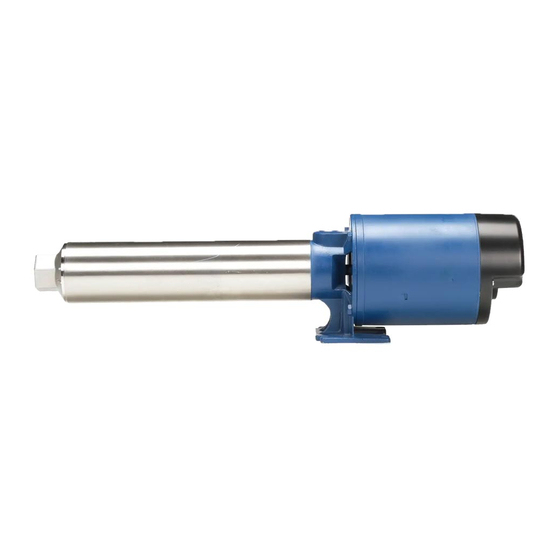
Pressure Booster Pumps
Description
Pressure booster pumps increase water pressure from city mains or private water systems.
Applications include providing high water pressure for washing buildings, dairy walls or
floors, hog parlors, poultry houses, rinsing or spray cooling equipment, lawn sprinkling and
insecticide spraying.
Single-phase models are equipped with a capacitor start, thermal protected motor. Three-
phase models require separate overload protection.
7.15
Figure 1
Pump Dimensions
60 Hz
HP
GPM
1/3
5
1/3*
5
1/2
5
1/2*
5
3/4
5
3/4
7
3/4*
7
1
10
1-1/2
10
1*
10
1*
10
1*
10
2
19
1-1/2*
19
2*
19
2
27
3
27
2*
27
3
27
2
35
3
35
1-1/2*
35
3*
35
*50Hz
1.44
"H" INLET
3.25
"C"
"F"
Stage
"C"
8
10.19
8
10.19
12
13.38
14
14.97
16
16.54
12
13.38
14
14.97
14
16.31
16
18.13
20
21.69
22
23.50
23
24.38
14
17.89
20
24.06
22
26.13
11
15.38
14
18.50
17
21.59
17
21.59
6
13.94
8
17.13
8
17.13
14
26.86
© 2020 FLINT & WALLING, INC. • 95 North Oak St. • Kendallville, IN 46755
flintandwalling.com
5.28
2 & 3HP
1Ø TEFC ONLY
4.88
TEFC ONLY
"J" DISCHARGE
3.88
3.75
6.50
F
TEFC
F&W
1 Phase
19.81
-
20.06
22.04
23.25
23.23
25.34
26.82
26.91
28.77
23.75
25.61
25.84
27.20
27.18
29.16
29.62
31.48
33.18
34.54
34.99
36.35
35.87
37.73
29.88
32.12
36.05
37.41
38.12
40.36
27.37
29.61
30.49
33.85
33.58
35.82
33.74
-
25.93
28.17
29.12
32.48
29.12
30.48
38.85
42.21
1
Unpacking
When unpacking the unit, inspect
carefully for any damage that may have
occurred during transit.
NOTE: Use pump with clear water only.
9.75
1-1/2 & 2HP 1Ø TEFC
ALL 3HP 1Ø
IL0391B
Chart A
H
3 Phase
-
.75
-
.75
24.10
.75
25.69
.75
27.51
.75
24.35
.75
25.94
.75
28.02
.75
30.07
.75
33.40
.75
35.21
.75
36.09
.75
30.87
.75
36.00
.75
39.11
.75
28.36
1.00
33.35
1.00
34.57
1.00
-
1.00
26.92
1.00
31.98
1.00
29.07
1.00
41.71
1.00
132934 F
J
.75
.75
.75
.75
.75
.75
.75
.75
.75
.75
.75
.75
.75
.75
.75
1.00
1.00
1.00
1.00
1.00
1.00
1.00
1.00
Advertisement
Table of Contents

Related Manuals for Flint & Walling PB0508S031


Summary of Contents for Flint & Walling PB0508S031
- Page 1 Operating Instructions & Parts Manual Please read and save these instructions. Read carefully before attempting to assemble, install, operate or maintain the product described. Protect yourself and others by observing all safety information. Failure to comply with instructions could result in personal injury and/or property damage! Retain instructions for future reference.
- Page 2 Powder- Pipe Pipe Stainless Steel Cast Iron Press. Coated Cast HP Stage Output - Gallons per Minute Fitted Fitted Iron Fitted 60Hz Models PB0508S031 ∆ PB0508C031 PB0508A031 10.2 PB0512S051 ∆ PB0512C051 PB0512A051 10.0 PB0516S071 ∆ PB0516C071 PB0516A071 10.2 PB0712S071 ∆...
- Page 3 Three Phase Motor Data Chart D Three Phase† 60/50 Hz 3450/2850 RPM Capacitor Start Factory Service Factor Motor Amps Locked Rotor Motor Amps Motor Connected Code Letter Voltage 230V 460V 230V 460V Motor Voltage 208-230/460 230V 1.75 19.0 208-230/460 230V 2.25 26.9 13.5...
-
Page 4: Pre-Installation
General Safety Information Protect electrical cord. Replace or repair damaged or worn cords immediately. Carefully read and follow all safety instructions in this manual and on pump. Keep safety labels in good condition. Replace Do not insert finger or any object into pump or motor missing or damaged safety labels. -
Page 5: Pump Installation
IMPORTANT: The entire system must No Air Leaks In Pipe Joint Compound No Sags Sags Allow Air Pockets Inlet Pipe Will Damage Plastic be air and water tight for efficient/proper operation. If Air Flows Installation Water Won’t PUMP INSTALLATION IMPORTANT: Pump is built to handle IL0419 clear water only;... - Page 6 Installation (Continued) Pump used to boost incoming city pressure (automatic operation). A pressure gauge installed in the Street Supply inlet pipe close to the inlet port, (See Figure 6) will show if enough Gate/ Main Power Box Union Check water is being supplied to the pump. Ball Valve Valve See Operation Section - Priming,...
- Page 7 Installation (Continued) Pump used to boost incoming pressure from a wall hydrant (manual operation). Ground motor Hose Adapter before connecting Wall Hydrant Pressure Gauge to electrical power supply. Pressure Relief Valve Failure to ground motor can cause Service Tee Hose Adapter severe or fatal High Pressure Reinforced Hose Inlet...
- Page 8 Installation (Continued) 3 Phase 3 Phase LOW VOLTAGE HIGH VOLTAGE GROUND LOW VOLTAGE HIGH VOLTAGE (WHEN REQ) T7 T1 LINE LINE LINE LINE IL1231 IL1229 Figure 11 - Wiring Diagram for Baldor TEFC 3 Phase motors Figure 13 - Wiring Diagram for Marathon TEFC 3 Phase motors 3 Phase 1 Phase...
-
Page 9: Motor Protection
Installation (Continued) local or United States National Electric Codes for proper fuse protection based on motor data chart (See Charts C, D and Wire Specific Wiring Procedure (Refer to Figures 9, 10, 11, 12, chart F). 13, 14 and Minimum Wire Size Chart). Operation a. - Page 10 Operation (Continued) Using the pipe wrench, remove the discharge head, turning CCW (counter clockwise). START - UP PROCEDURE With the strap wrench, loosen the barrel, turning CCW Once the preceding instructions have been completed, the (counter clockwise). DO NOT use pipe wrench on pump pump can be started.
-
Page 11: Motor Replacement
Maintenance (Continued) PUMP REASSEMBLY Before reassembling the pump, carefully inspect the component IMPORTANT: Do not scratch seal face. parts of the cartridge (stage) assembly, looking for damage, Dispose of cardboard washer and recheck seal face to be wear or heat distortion. Pay careful attention to spacing sure it is free of dirt, foreign particles, scratches and grease. -
Page 12: Troubleshooting Chart
Troubleshooting Chart Symptom Possible Cause(s) Corrective Action Pump won’t 1. Blown fuse or open circuit breaker 1. Replace fuse or close circuit breaker. See wire size chart for start or run proper break/fuse size at full speed 2. Power supply in OFF position 2. - Page 13 Booster Pump Parts Drawing ITEM NO. DESCRIPTION Motor †Governor †Switch Motor Seal, Rotary Barrel Discharge Head Discharge Bearing O-ring (2) Plate, Diffuser Impeller Diffuser Diffuser Bearing Shim as Required Shaft and Coupling Assembly IL0127 Mounting Ring Hex Head Bolts (4) †MotorAccess Cover Figure 19 †Screws, Access Cover (2)
- Page 14 PRESSURE BOOSTER PUMP REPAIR PARTS FORM NO. FW0045 1020 (For Pricing Refer To Repair Parts Price List) SUPERSEDES 1114 Replacement Motors POWDER STAINLESS POWDER STAINLESS ITEM REPLACEMENT MOTORS CAST IRON CAST IRON COATED STEEL COATED STEEL SINGLE PHASE 60 HZ THREE PHASE 60 HZ ODP NEMA J 1/3 HP 98J103...
- Page 15 PRESSURE BOOSTER PUMP REPAIR PARTS FORM NO. FW0046 1020 (For Pricing Refer To Repair Parts Price List) SUPERSEDES 1114 POWDER STAINLESS ITEM DESCRIPTION CAST IRON COATED STEEL 5 - 7 - 10 - 19 GPM, Discharge Head 3/4” NPT 132000 136905 136640 60 HZ &...
Need help?
Do you have a question about the PB0508S031 and is the answer not in the manual?
Questions and answers