Table of Contents
Advertisement
Quick Links
8 Channel Video Transmit Unit with 9 Bi-directional Data
and Audio Channels for a Multimode Fibre Link
The AMG4687B is a standalone eight channel video transmit unit designed to transmit 8 video signals
and transmit and receive up to 9 data or audio signals over two Multimode fibres. The 9 data/audio
channel interfaces, whether RS232, RS422, RS485, 20mA, TTL, Contact Closure, Lonworks or Audio,
are defined at manufacture by the addition of daughter boards fitted onto the Data Expansion Board B.
The AMG4687B is designed to be powered using an AMG2003 standalone power supply.
The AMG4687B is designed to operate with AMG4688B or rackmount equivalent AMG4688BR eight
channel video receive unit in a point to point configuration.
AMG Systems Ltd. reserves the right to make changes to this
document without notice. The information herein is believed to
be accurate. No responsibility is assumed by AMG for its use.
AMG4687B
Instruction Manual
Page 1 of 12
AMG4687B Instruction Sheet D18111-
01.doc
Advertisement
Table of Contents

Related Manuals for AMG AMG4687B


Summary of Contents for AMG AMG4687B
- Page 1 Audio Channels for a Multimode Fibre Link The AMG4687B is a standalone eight channel video transmit unit designed to transmit 8 video signals and transmit and receive up to 9 data or audio signals over two Multimode fibres. The 9 data/audio channel interfaces, whether RS232, RS422, RS485, 20mA, TTL, Contact Closure, Lonworks or Audio, are defined at manufacture by the addition of daughter boards fitted onto the Data Expansion Board B.
-
Page 2: Table Of Contents
Removal / replacement from / to the Case..................10 Safety Maintenance and Repair AMG Systems Ltd. reserves the right to make changes to this Page 2 of 12 AMG4687B Instruction Sheet D18111- document without notice. The information herein is believed to 01.doc... -
Page 3: Introduction
It also receives up to 9 data and audio channels transmitted from the AMG4688B. Optical Connection The AMG4687B is connected as illustrated below when used with an AMG4688B receive unit acting as a point to point system. AMG Systems Ltd. reserves the right to make changes to this... -
Page 4: Connections
For the data or audio channels to be present, appropriate data daughter boards must be fitted onto the data expansion board slots. AMG Systems Ltd. reserves the right to make changes to this Page 4 of 12 AMG4687B Instruction Sheet D18111- document without notice. -
Page 5: Data And Audio Channel Configuration
RS485 bus high (+5 volts) and the other arm low (0 volts) using high value resistors within the third party equipment. In order to ensure that the AMG equipment detects a tri-state condition, then these resistors should have a value above 5kΩ. If the third party bias resistors are less the 750Ω... -
Page 6: Bank B Data
Data and Audio Channel Configuration The data expansion board slots are accessed by removing the AMG unit from its case. A data channel is active when a daughter board is installed in the required data channel slot. Each data interface board enables one bi-directional channel. -
Page 7: Data And Audio Connections Bank B
See Data or Audio Daughter Board Instruction Sheet for meaning of Audio/Data IN+, Audio/Data IN- Audio/Data OUT+, and Audio/Data OUT- for each data type. AMG Systems Ltd. reserves the right to make changes to this Page 7 of 12 AMG4687B Instruction Sheet D18111- document without notice. -
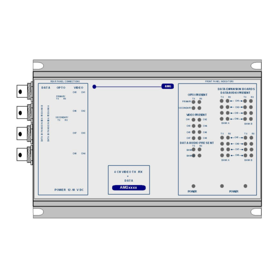
Page 8: Front Panel Indicators
OUT+ logic one (-V) present on OUT+ This represents the data signals being received on the optical fibre AMG Systems Ltd. reserves the right to make changes to this Page 8 of 12 AMG4687B Instruction Sheet D18111- document without notice. - Page 9 > 0dBm (overload at +6dBm) audio not present or < -40dBm This represents the audio signals being received from the optical fibre. AMG Systems Ltd. reserves the right to make changes to this Page 9 of 12 AMG4687B Instruction Sheet D18111- document without notice.
-
Page 10: Physical Information
Mounting Details The AMG unit is supplied with a clip-on mounting bracket which should be attached to a panel or wall using 2 off 4.0mm screws. The unit is clipped into the mounting bracket, and is then held firmly in position. - Page 11 This page is intentionally blank. AMG Systems Ltd. reserves the right to make changes to this Page 11 of 12 AMG4687B Instruction Sheet D18111- document without notice. The information herein is believed to 01.doc be accurate. No responsibility is assumed by AMG for its use.
- Page 12 This page is intentionally blank. AMG Systems Ltd. reserves the right to make changes to this Page 12 of 12 AMG4687B Instruction Sheet D18111- document without notice. The information herein is believed to 01.doc be accurate. No responsibility is assumed by AMG for its use.
Need help?
Do you have a question about the AMG4687B and is the answer not in the manual?
Questions and answers