Table of Contents
Advertisement
Quick Links
8 Channel Video Transmit Unit with 9 Bi-directional Data
and Audio Channels and Ethernet for a Multimode Fibre
The AMG4687BER is a rackmount eight channel video transmit unit designed to transmit 8 video
signals and transmit and receive up to 9 data or audio signals plus full duplex 100BaseT Ethernet
connectivity over two Multimode fibres. The 9 data/audio channel interfaces, whether RS232, RS422,
RS485, 20mA, TTL, Contact Closure, Lonworks or Audio, are defined at manufacture by the addition
of daughter boards fitted onto the Data Expansion Board B.
The AMG4687BER is designed to plug into an AMG2005 or AMG2009 subrack, which in turn fits into
a 19" rack system.
The AMG4687BER is designed to operate with AMG4688BE or rackmount equivalent AMG4688BER
eight channel video receive unit in a point to point configuration.
AMG Systems Ltd. reserves the right to make changes to this
document without notice. The information herein is believed to
be accurate. No responsibility is assumed by AMG for its use.
AMG4687BER
Instruction Manual
Link
Page 1 of 12
AMG4687BER Instruction Sheet
D18624-02.doc
Advertisement
Table of Contents

Related Manuals for AMG AMG4687BER


Summary of Contents for AMG AMG4687BER
- Page 1 RS485, 20mA, TTL, Contact Closure, Lonworks or Audio, are defined at manufacture by the addition of daughter boards fitted onto the Data Expansion Board B. The AMG4687BER is designed to plug into an AMG2005 or AMG2009 subrack, which in turn fits into a 19" rack system.
-
Page 2: Table Of Contents
Removal / replacement from / to the Case..................12 Safety Maintenance and Repair AMG Systems Ltd. reserves the right to make changes to this Page 2 of 12 AMG4687BER Instruction Sheet document without notice. The information herein is believed to D18624-02.doc... -
Page 3: Introduction
Ethernet connectivity is also provided between the two units. Optical Connection The AMG4687BER is connected as illustrated below when used with an AMG4688BER 8-channel receive unit acting as a point to point system. AMG Systems Ltd. reserves the right to make changes to this... -
Page 4: Connections
Data/Audio Channels – BANK A ..Not Used Data/Audio Channels – BANK B ..8 channels Connector ..........37-way D-Type female connector - shielded. AMG Systems Ltd. reserves the right to make changes to this Page 4 of 12 AMG4687BER Instruction Sheet document without notice. The information herein is believed to D18624-02.doc... - Page 5 For the data or audio channels to be present, appropriate data daughter boards must be fitted onto the data expansion board slots. AMG Systems Ltd. reserves the right to make changes to this Page 5 of 12 AMG4687BER Instruction Sheet document without notice.
-
Page 6: Data And Audio Channel Configuration
RS485 bus high (+5 volts) and the other arm low (0 volts) using high value resistors within the third party equipment. In order to ensure that the AMG equipment detects a tri-state condition, then these resistors should have a value above 5kΩ. If the third party bias resistors are less the 750Ω... -
Page 7: Bank B Data
Data and Audio Channel Configuration The data expansion board slots are accessed by removing the AMG unit from its case. A data channel is active when a daughter board is installed in the required data channel slot. Each data interface board enables one bi-directional channel. -
Page 8: Data And Audio Connections Bank B
See Data or Audio Daughter Board Instruction Sheet for meaning of Audio/Data IN+, Audio/Data IN- Audio/Data OUT+, and Audio/Data OUT- for each data type. AMG Systems Ltd. reserves the right to make changes to this Page 8 of 12 AMG4687BER Instruction Sheet document without notice. -
Page 9: Ethernet Operation
Ethernet Operation In order for the AMG system to transmit Ethernet signals, an onboard RJ45 Ethernet interface or X16003 Ethernet interface adaptor should be fitted to both the Transmit unit and the Receive unit. The Ethernet interface can operate at either 10Mbits/s half duplex, or 100Mbit/s full duplex, and data is transmitted from one port the other port with the minimum of delay or buffering. -
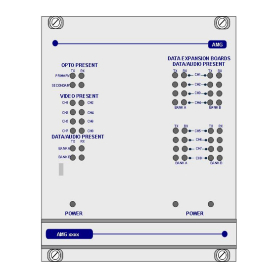
Page 10: Front Panel Indicators
OUT+ logic one (-V) present on OUT+ This represents the data signals being received on the optical fibre AMG Systems Ltd. reserves the right to make changes to this Page 10 of 12 AMG4687BER Instruction Sheet document without notice. - Page 11 > 0dBm (overload at +6dBm) audio not present or < -40dBm This represents the audio signals being received from the optical fibre. AMG Systems Ltd. reserves the right to make changes to this Page 11 of 12 AMG4687BER Instruction Sheet document without notice.
-
Page 12: Physical Information
There are no user serviceable parts within AMG products. See unit data sheet for full specification. In case of problem or failure, please call your local support centre or contact: AMG Systems Ltd. at 3 The Omega Centre, Stratton Business Park, Biggleswade, Beds., SG18 8QB, UK.
Need help?
Do you have a question about the AMG4687BER and is the answer not in the manual?
Questions and answers