Advertisement
Quick Links
Hangzhou Ruideng Technology Co., Ltd.
OPERATING MANUAL
DPH5005 Digital Power Supply Upper Computer
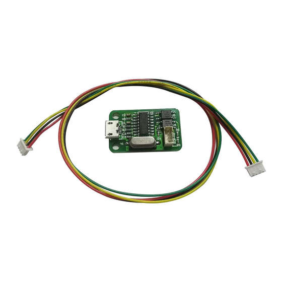
1 Communication Board Connetion
1.1 Wire Communication Board Connection
Open data package, double click CH341SER.EXE and install drive
program of communication board.
After installation, please use the attach cable to connect
digital power supply with communication board, and use USB cable to
connect Micro UBB port with PC.
Digital power supply communication data setting:
Keep pressing ↑button to power on, then enter into data setting
interface. Press ↑or↓ to choose data, then press knob to adjust the
value. After adjustment, press twice shortly SET key to exist data
setting, and those data are stored automatically.
COMM: Communication stitch setting, ON represents opening
communication, OFF represents closing communication.
ADDR: Digital power supply address code, range 001-255.
BAUD: Communication baud rate, 2400,4800,9600,19200 adjusting.
BPIN: Bluetooth PIN Code Pairing, 0000-9999, useless for wire
communication.
(For Win7 and above)
Advertisement

Related Manuals for RuiDeng DPH5005


Summary of Contents for RuiDeng DPH5005
- Page 1 Hangzhou Ruideng Technology Co., Ltd. OPERATING MANUAL DPH5005 Digital Power Supply Upper Computer (For Win7 and above) 1 Communication Board Connetion 1.1 Wire Communication Board Connection Open data package, double click CH341SER.EXE and install drive program of communication board. After installation, please use the attach cable to connect digital power supply with communication board, and use USB cable to connect Micro UBB port with PC.
- Page 2 Hangzhou Ruideng Technology Co., Ltd. 1.2 Bluetooth communication board communication board is 2.0 protocol. Please Bluetooth Bluetooth use the attached cable to connect digital power supply with bluetooth communication board. After power on, the LED on the board will blink; so the bluetooth is in the state of searching.
- Page 3 Hangzhou Ruideng Technology Co., Ltd. After searching, the bluetooth device will show and the last 3 bit 001 of name represent address code of digital power supply. When connect bluetooth device, please enter pairing code, the default password is 1234.
- Page 4 Hangzhou Ruideng Technology Co., Ltd.
- Page 5 Hangzhou Ruideng Technology Co., Ltd. After connecting, the system will download and install Virtual serial port driver of bluetooth automatically. The smaller number CMO is what we use, eg COM3, we need to choose COM3 on upper computer. If we need to adjust communication data, the operation is similar as wire communication.
- Page 6 Hangzhou Ruideng Technology Co., Ltd. Double click setup.exe and install upper computer software. Select installation directory, and click next. Click next to install, and wait installation to complete.
- Page 7 Hangzhou Ruideng Technology Co., Ltd.
-
Page 8: Software Operating
Hangzhou Ruideng Technology Co., Ltd. 3 Software operating Double click short-cut icon on the desk to open upper computer software. After opening software, select slave address, and cli serial port, baud rate and ck online to communicate. After online, all the button of digital power supply are locked automatically;... - Page 9 Hangzhou Ruideng Technology Co., Ltd.
- Page 10 DPH5005 CNC Power Communication Protocol V1.2 Communication protocol overview: The communication protocol for this device is specifically MODBUS RTU. This can be used via RS232, RS485 or Bluetooth serial interface. Note, This product only supports MODBUS RTU Function Codes 0x03 (03H), 0x06 (06H), 0x10 (10H) II.
- Page 11 1.3 Data area: The data bytes contain any additional information that the slave will need to perform the function. For example, function code 03 will request the slave to read holding registers and respond with their contents. The data field must contain the information telling the slave which register to start at and how many registers to read.
- Page 12 Shortcut to bring up the EXTRACT_M 0023H required data set U-SET Voltage settings 0050H I-SET Current setting 0051H S-OVP Over-voltage protection value 0052H S-OCP Over-current protection value 0053H S-OPP Over power protection 0054H B-LED Backlight brightness levels 0055H M-PRE Memory Preset Number 0056H S-INI Power output switch...
- Page 13 Three examples of communication using the three available MODBUS Functions Codes supported on this device. (0x03) (0x06) and (0x10) 1 : Read the displayed output voltage and current value. (Using Function 0x03) Message format sent from Host: Number of Host sends Information sent Notes bytes...
- Page 14 Message format returned from Slave From machine Number The information Notes responses of bytes returned Slave address From Slave address 01H Function code Write multiple registers Register the starting 0000H Register starting address address Number of registers 0002H 2 registers written to written CRC Code: 41C8H...
Need help?
Do you have a question about the DPH5005 and is the answer not in the manual?
Questions and answers