
Related Manuals for Murata WIT2410


Summary of Contents for Murata WIT2410
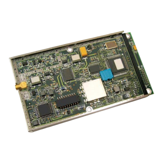
- Page 1 WIT2410 2.4GHz Spread Spectrum Wireless Industrial Transceiver Integration www.murata.com ©2015 by Murata Electronics N.A., Inc. WIT2410 Integration Guide (2015/04/27)
- Page 2 Notice to users/installers using the 24 dBi parabolic dish antenna in conjunction with all Murata RF products. FCC rules limit the use of this antenna, when connected to Murata RF products for point-to-point applications only. It is the responsibility of the installer to ensure that the system is prohibited from being used in point-to-multipoint applications, omni-directional applications, and applications where there are multiple co-located intentional radiators transmitting the same information.
- Page 3 Use of the WIT2410 in France When used in France, the WIT2410 can only be operated with the France hopping pattern selected. This is accomplished by setting the pe parameter to 1. Refer to European Union Settings in this manual for details.
-
Page 4: Table Of Contents
5.2. Network Commands ......................23 5.3. Protocol Commands......................26 5.4. Status Commands ......................29 5.5. Memory Commands ......................30 5.6. Modem Command Summary.....................31 6. WIT2410 DEVELOPER’S KIT ....................32 7. WinCOM...........................33 7.1. Starting the program ......................35 www.murata.com ©2015 by Murata Electronics N.A., Inc. WIT2410 Integration Guide (2015/04/27) - Page 5 9.3. Approved Antennas ......................47 9.4. Technical Support ......................48 9.5. Reference Design.......................49 9.6.1. Mechanical Drawing – WIT2410M4 (Pins Down) ............50 9.6.2. Mechanical Drawing – WIT2410S4 (Pins Up)...............51 10. Warranty ..........................52 www.murata.com ©2015 by Murata Electronics N.A., Inc. WIT2410 Integration Guide (2015/04/27)
-
Page 6: Introduction
1. INTRODUCTION The WIT2410 radio transceiver provides reliable wireless connectivity for either point-to-point or multipoint applications. Frequency hopping spread spectrum technology ensures maximum resistance to noise and multipath fading and robustness in the presence of interfering signals, while operation in the 2.4GHz ISM band allows license-free use and worldwide compliance. -
Page 7: Frequency Hopping Vs. Direct Sequence
Page 2 of 52 www.murata.com ©2015 by Murata Electronics N.A., Inc. WIT2410 Integration Guide (2015/04/27) - Page 8 Page 3 of 52 www.murata.com ©2015 by Murata Electronics N.A., Inc. WIT2410 Integration Guide (2015/04/27)
- Page 9 This regulatory convenience alone has been a large motivation for the industry-wide move toward spread spectrum. Page 4 of 52 www.murata.com ©2015 by Murata Electronics N.A., Inc. WIT2410 Integration Guide (2015/04/27)
-
Page 10: Radio Operation
(protocol mode 0). The amount of data that the base station can transmit per hop is determined by the base slot Page 5 of 52 www.murata.com ©2015 by Murata Electronics N.A., Inc. WIT2410 Integration Guide (2015/04/27) -
Page 11: Data Transmission
2.2. Data Transmission The WIT2410 supports two network configurations: point-to-point and point-to- multipoint. In a point-to-point network, one radio is set up as the base station and the other radio is set up as a remote. In a point-to-multipoint network, a star topology is used with the radio set up as a base station acting as the central communications point and all other radios in the network set up as remotes. -
Page 12: Point-To-Multipoint
The WIT2410 has a point-to-point direct mode which fixes the remote radio’s handle at 30H. This mode is recommended for point-to-point applications, especially if the remote is likely to periodically leave and re-enter the coverage area of the base. -
Page 13: Tdma Operation
For applications needing guaranteed bandwidth availability, the TDMA operation of the WIT2410 can meet this requirement. In the WIT2410 TDMA scheme, each remote has an assigned time slot during which it can transmit. The base station time slot is set independently of the remote time slots through the Set Base Slot Size command. - Page 14 = 18 bytes of data per hop. 17.36µs Note that the 18 bytes is the actual number of data bytes that can be sent. If the WIT2410 is using a protocol mode, the packet overhead does not need to be considered. So in this...
-
Page 15: Full Duplex Communication
WIT2410 can still communicate reliably. Data input to the WIT2410 is broken up by the radio into packets. A 24-bit checksum is attached to each packet to verify that it was correctly received. If the packet is received... -
Page 16: Modes Of Operation
2.3. Modes of Operation 2.3.1. Control and Data Modes The WIT2410 has two modes of operation: Control mode and Data mode. When in Control Mode, the various radio and modem parameters can be modified. When in Data Mode, only data can be transmitted. The default mode is Data Mode. There are two ways to enter Control Mode. -
Page 17: Low Power Mode And Duty Cycling
To compensate for the variations in nominal baud rates, the WIT2410 supports an RF flow control mode for point-to-point operation. In this mode, when the receive buffer of the receiving WIT2410 is close to full, the receiving WIT2410 stops acknowledging transmissions. The transmitting radio is set to infinite retries which invokes the RF flow control mode (See Set Packet Attempts Limit in Section 5.3). -
Page 18: Co-Existing With 802.11B Networks
2.3.5. Co-Existing with 802.11b Networks In some cases, if a WIT2410-based network is located in close proximity to an 802.11b network, the WIT2410-based network can interfere with the 802.11b network. To avoid causing this interference, the WIT2410 radio supports a selection of hopping patterns that avoid the various 802.11b direct sequence channels. -
Page 19: Protocol Modes
The remotes may still use transparent mode without formatting to send data to the base, if desired. The WIT2410 supports 10 protocol formats that are described in detail below. The protocol format is selected through the Set Protocol Mode command. - Page 20 This is the packet format used by the WIT2400. This allows legacy software to operate the WIT2410 with a minimum of changes. Note however, that since different air data rates are used, WIT2410s and WIT2400s cannot be mixed in a network.
-
Page 21: Note On Using Protocol Mode 4
In the WIT2410, remotes are distinguished by their factory-assigned serial number. When using protocol Mode 4 in the WIT2410, the static address of the WIT2400 is replaced with the current handle of the WIT2410. In point-to-multipoint configurations, a remote’s handle is not guaranteed to remain the same if the remote drops link with the base and then re-establishes link. -
Page 22: Data Packet
The radio will not break up a packet over multiple hops. Packets with a data length greater than maximum data length Page 17 of 52 www.murata.com ©2015 by Murata Electronics N.A., Inc. WIT2410 Integration Guide (2015/04/27) -
Page 23: Connect Packet
When a remote goes out of range or roams to another cell, the base issues a disconnect packet to indicate that the remote is no longer available. Page 18 of 52 www.murata.com ©2015 by Murata Electronics N.A., Inc. WIT2410 Integration Guide (2015/04/27) -
Page 24: Modem Interface
4. MODEM INTERFACE Electrical connection to the WIT2410 is made through a 16-pin male header on the modem module. The signals are 3.3 volt signals and form an RS-232 style asynchronous serial interface. The table below provides the connector pinout. -
Page 25: Interfacing To 5 Volt Systems
4.1. Interfacing to 5 Volt Systems The modem interface signals on the WIT2410 are 3.3 volt signals. To interface to 5 volt signals, the resistor divider network shown below must be placed between the 5 volt signal outputs and the WIT2410 signal inputs. The output voltage swing of the WIT2410 3.3 volt signals is sufficient to drive 5 volt logic inputs. -
Page 26: Power-On Reset Requirements
4.4. Power-On Reset Requirements The WIT2410 has an internal reset circuit that provides a reset signal to the microprocessor if the supply voltage to the WIT2410 falls below 2.7 volts. Operation of the microprocessor at voltages below this voltage is unspecified and can result in corruption of the program memory. -
Page 27: Modem Commands
5. MODEM COMMANDS The WIT2410 is configured and controlled through a series of commands. These commands are sent to the modem directly when the modem is in Control Mode when the modem is in Data Mode if the escape sequence is enabled. The command syntax is the same for either method, a one- or two-letter command followed by one or more parameters. -
Page 28: Network Commands
When using a protocol mode, make sure to count in packet overhead when calculating network performance. Refer to the section on Protocol Modes for details on each format. 5.2. Network Commands Network commands are used to set up a WIT2410 network and to set radio addressing and configuration. Command... - Page 29 Set Hopping Pattern The WIT2410 has 64 preprogrammed hopping patterns (also referred to as network numbers). By using different hopping patterns, nearby or co-located networks can avoid interfering with each other’s transmissions. Even if both networks tried to use the same frequency, on the next hop they would be at different frequencies.
- Page 30 1.4mi/2.3km 2.0mi/3.3km 2.8mi/4.7km 4.4mi/7.3km 5.0mi/8.3km 5.8 mi/9.7km 6.4mi/10.7km 7.0mi/11.7km 7.8mi/13.0km 9.4mi/15.7km 10.0mi/16.7km 10.8mi/18.0km 19.3mi/32.3km 20.0mi/33.3km 20.8mi/34.7km 24.4mi/40.7km 25.0mi/41.7km 25.8mi/43.0km Optimal 'dx' setting for various distances. Page 25 of 52 www.murata.com ©2015 by Murata Electronics N.A., Inc. WIT2410 Integration Guide (2015/04/27)
-
Page 31: Protocol Commands
French regulatory standards. When set to 2, sets appropriate operation for Spain. When set to 3, sets appropriate operation for Japan. This setting Page 26 of 52 www.murata.com ©2015 by Murata Electronics N.A., Inc. WIT2410 Integration Guide (2015/04/27) - Page 32 Additional 25 channel bands have been provided to avoid hopping through the various 802.11b channels. If the WIT2410 is to be used in close proximity to 802.11b networks, these alternative hopsets can be used to avoid interfering with the 802.11b networks.
- Page 33 When redundant transmit mode is used, receiving radios will discard all subsequent retransmissions once the transmission has been successfully received. Thus the receiving host will receive just one copy of the transmission. Page 28 of 52 www.murata.com ©2015 by Murata Electronics N.A., Inc. WIT2410 Integration Guide (2015/04/27)
-
Page 34: Status Commands
5.4. Status Commands These commands deal with general interface aspects of the operation of the WIT2410. Command Description zb[?|0|1] Banner Display Disable 0 = disabled 1 = enabled (default) zc[?|0..2] Set Escape Sequence Mode 0 = disabled 1 = once after reset (default) 2 = unlimited times Read factory serial number high byte. -
Page 35: Memory Commands
Display Modified Parameters Recall Factory Defaults Resets the WIT2410 to its factory default state. This is useful for testing purposes or if there is a problem in operation of the system and the configuration is suspect. Use the Store Memory command afterwards if you wish the factory default settings to be remembered the next time you cycle power or reset the radio. -
Page 36: Modem Command Summary
For example, given the string wn[?|00..3f], legal commands would be wn?, wn0, wn3, and wn2a. Most commands which set a parameter also have a ? option which displays the current parameter setting; e.g., wn?. Page 31 of 52 www.murata.com ©2015 by Murata Electronics N.A., Inc. WIT2410 Integration Guide (2015/04/27) -
Page 37: Wit2410 Developer's Kit
The pinout is provided in Section 7.3. The modems can be used with just a three wire connection. Transmit data, receive data and ground are the three required connections. Note that in this configuration, no flow control is available as the WIT2410 does not support software flow control. -
Page 38: Wincom
Software Tools directory on the Manuals and Software CD and double- click on wincom2.1.exe follow the installation wizard. Once it has installed, open WinCOM by double-clicking on the WinCOM icon on the desktop. Page 33 of 52 www.murata.com ©2015 by Murata Electronics N.A., Inc. WIT2410 Integration Guide (2015/04/27) - Page 39 The Help menu displays the About screen which lists the version number, hardware and software information for the system being used. Page 34 of 52 www.murata.com ©2015 by Murata Electronics N.A., Inc. WIT2410 Integration Guide (2015/04/27)
-
Page 40: Starting The Program
Unless the “Echo” box is checked the typed data will not be displayed in the WinCOM window of the sending radio. Page 35 of 52 www.murata.com ©2015 by Murata Electronics N.A., Inc. WIT2410 Integration Guide (2015/04/27) - Page 41 When the radio is linked to another radio, a communications test can be run by clicking on the Transmit button or pressing the F6 key. Whatever ASCII string is in the Transmit String window will be transmitted as shown below. Page 36 of 52 www.murata.com ©2015 by Murata Electronics N.A., Inc. WIT2410 Integration Guide (2015/04/27)
- Page 42 The Clear Screen button deletes all the text in the display window. The Clear CTS and Clear DCD buttons reset the respective changes counters to zero. Page 37 of 52 www.murata.com ©2015 by Murata Electronics N.A., Inc. WIT2410 Integration Guide (2015/04/27)
-
Page 43: Function Keys
WinCOM can communicate at new data rate without having to exit and re-enter WinCOM. Sets data rate of PC serial port to next lower value. Value is displayed in PgDn status line. Page 38 of 52 www.murata.com ©2015 by Murata Electronics N.A., Inc. WIT2410 Integration Guide (2015/04/27) -
Page 44: Wincom Tools
The third allows for checking of available Comm Ports and is useful for refreshing the list. The fourth, Transmit Tools allows for testing of the Transparent, WIT2410/WIT910 or WIT2411 settings. Parameters related to how the transmission will take place can be set... - Page 45 Configuration commands need to have wait periods between them. The list of commands and their definitions is below: Page 40 of 52 www.murata.com ©2015 by Murata Electronics N.A., Inc. WIT2410 Integration Guide (2015/04/27)
-
Page 46: Script Commands
Cycling power or toggling DTR will return the radio to data mode. WinCOM prompts you to select the desired .wcr file. Opening the script file causes it to executed immediately. Page 41 of 52 www.murata.com ©2015 by Murata Electronics N.A., Inc. WIT2410 Integration Guide (2015/04/27) - Page 47 Finally, the eighth tool is Save to File which launches a Save As dialog that allows any data received to be loaded into a file. Page 42 of 52 www.murata.com ©2015 by Murata Electronics N.A., Inc. WIT2410 Integration Guide (2015/04/27)
-
Page 48: Demonstration Procedure
6. For a range test, disconnect the remote station from the computer and power supply. The DCD indicator should remain lit as long as the base station is in range.. 7. Exit COM24 by pressing the ESC key. Page 43 of 52 www.murata.com ©2015 by Murata Electronics N.A., Inc. WIT2410 Integration Guide (2015/04/27) -
Page 49: Troubleshooting
Can’t enter modem control mode. Make sure the host data rate is correct. The WIT2410 defaults to 9600 bps asynchronous. Evaluation units do not have external access to the CFG_SEL signal; you must use the :wit2410 power-on escape sequence to access modem control mode. - Page 50 OEM Module is in an unknown state. Use the command to restore the factory defaults. Note that the serial baud rate must be known for the module to receive this command. Page 45 of 52 www.murata.com ©2015 by Murata Electronics N.A., Inc. WIT2410 Integration Guide (2015/04/27)
-
Page 51: Appendices
Huber/Suhner: 85 MMCX 50-0-1 Mating Huber/Suhner: 11 MMCX-50-2-3 (straight) Huber/Suhner: 16 MMCX-50-2-2 (rt. angle) Data/Power Connector: Samtec: DIS5-108-51-L-D Mating Samtec: CLP-108-02-G-D (PCB mount) Samtec: FFSD-08 (IDC cable) Page 46 of 52 www.murata.com ©2015 by Murata Electronics N.A., Inc. WIT2410 Integration Guide (2015/04/27) -
Page 52: Serial Connector Pinouts
RXD and connect ground. The HN-510 can operate with just these three wires connected. However, as the WIT2410 does not support software flow control, there will be no flow control in this mode. If the DTE device fails to respond, connect DCD from the HN-510 to the DTR and RTS inputs to activate the DCE device whenever the WIT2410 asserts carrier. -
Page 53: Technical Support
9.4. Technical Support For technical support call Murata at (678) 684-2004 between the hours of 8:30AM and 5:30PM Eastern Time. Page 48 of 52 www.murata.com ©2015 by Murata Electronics N.A., Inc. WIT2410 Integration Guide (2015/04/27) -
Page 54: Reference Design
V CC 3.3V FORCEON If using a 5.0V converter use the following circuit for TXD,DTR,RTS FORCEOFF INVA LID MA X3 238 TXD_5V TXD_3.3V 2200 4300 Page 49 of 52 www.murata.com ©2015 by Murata Electronics N.A., Inc. WIT2410 Integration Guide (2015/04/27) -
Page 55: Mechanical Drawing - Wit2410M4 (Pins Down)
9.6.1. Mechanical Drawing – WIT2410M4 (Pins Down) Page 50 of 52 www.murata.com ©2015 by Murata Electronics N.A., Inc. WIT2410 Integration Guide (2015/04/27) -
Page 56: Mechanical Drawing - Wit2410S4 (Pins Up)
9.6.2. Mechanical Drawing – WIT2410S4 (Pins Up) Page 51 of 52 www.murata.com ©2015 by Murata Electronics N.A., Inc. WIT2410 Integration Guide (2015/04/27) -
Page 57: Warranty
SUPPLYING OF THE GOODS. THE FOREGOING WARRANTY EXTENDS TO BUYER ONLY AND SHALL NOT BE APPLICABLE TO ANY OTHER PERSON OR ENTITY INCLUDING, WITHOUT LIMITATION, CUSTOMERS OF BUYERS. Page 52 of 52 www.murata.com ©2015 by Murata Electronics N.A., Inc. WIT2410 Integration Guide (2015/04/27)
Need help?
Do you have a question about the WIT2410 and is the answer not in the manual?
Questions and answers