Table of Contents
Advertisement
Quick Links
Certification Exhibit
FCC ID: HSW-DNT90E
IC: 4492A-DNT90E
FCC Rule Part: 15.247
IC Radio Standards Specification: RSS-247
ACS Project Number: 16-0152
Manufacturer: Murata Electronics North America
Models: DNT90EC, DNT90EP
Manual
5015 B.U. Bowman Drive Buford, GA 30518 USA Voice: 770-831-8048 Fax: 770-831-8598
Advertisement
Table of Contents

Related Manuals for Murata DNT90E Series


Summary of Contents for Murata DNT90E Series
- Page 1 Certification Exhibit FCC ID: HSW-DNT90E IC: 4492A-DNT90E FCC Rule Part: 15.247 IC Radio Standards Specification: RSS-247 ACS Project Number: 16-0152 Manufacturer: Murata Electronics North America Models: DNT90EC, DNT90EP Manual 5015 B.U. Bowman Drive Buford, GA 30518 USA Voice: 770-831-8048 Fax: 770-831-8598...
- Page 2 DNT90E Series 900 MHz Spread Spectrum Wireless Transceivers Integration Guide www.Murata.com Technical support +1.678.684.2000 Page 1 of 80 RF Product Department. E-mail: tech_sup@murata.com DNT90E Integration Guide - 04/13/16...
- Page 3 3) Connect the equipment into an outlet on a circuit different from that to which the receiver is connected, 4) Consult the dealer or an experienced radio/TV technician for help. Warning: Changes or modifications to this device not expressly approved by MURATA could void the user’s authority to operate the equipment.
- Page 4 OMNI095 Omnidirectional Dipole Antenna, 5 dBi YAGI099 Directional Antenna, 6 dBi See Section 6.8 of this manual for regulatory notices and labeling requirements. Changes or modifica- tions to a DNT90E not expressly approved by MURATA may void the user’s authority to operate the module. www.Murata.com Technical support +1.678.684.2000...
-
Page 5: Table Of Contents
Mounting and Enclosures ......................31 Labeling and Notices ....................... 32 DNT90E Protocol-formatted Messages..................33 Protocol Formats........................33 Message Types........................33 Message Format Details ......................34 www.Murata.com Technical support +1.678.684.2000 Page 4 of 80 RF Product Department. E-mail: tech_sup@murata.com DNT90E Integration Guide - 04/13/16... - Page 6 Ordering Information ........................ 74 10.3 Technical Support ........................74 10.4 DNT90E Mechanical Specifications..................75 10.5 DNT90E Development Board Schematic................. 77 11.0 Warranty............................80 www.Murata.com Technical support +1.678.684.2000 Page 5 of 80 RF Product Department. E-mail: tech_sup@murata.com DNT90E Integration Guide - 04/13/16...
-
Page 7: Dnt90E Introduction
This allows the signal to be reconstructed even though part of it may be lost or corrupted in transmission. www.Murata.com Technical support +1.678.684.2000 Page 6 of 80 RF Product Department. -
Page 8: Why Spread Spectrum
Forms of spread spectrum - direct sequence and frequency hopping Figure 1.1.2 www.Murata.com Technical support +1.678.684.2000 Page 7 of 80 RF Product Department. -
Page 9: Frequency Hopping Versus Direct Sequence
Point- to-point systems are often used to replace wired serial connections. Point-to-point systems are also used to transmit switch positions or analog signals from one location to another. Figure 2.1.1 www.Murata.com Technical support +1.678.684.2000 Page 8 of 80 RF Product Department. -
Page 10: Dnt90E System Overview
The trade-off in store-and-forward systems is longer delivery times due to receiving and retransmitting a message several times. Store-and-forward systems are especially useful in applica- tions such as agriculture where data is only collected periodically. www.Murata.com Technical support +1.678.684.2000 Page 9 of 80 RF Product Department. -
Page 11: Rf Channel Access
If a child radio does not see its address in the next beacon following its transmission, it again randomly selects an open slot and retransmits its data. During times when there are no open slots, a child radio www.MURATA.com Technical support +1.678.684.2000 Page 10 of 80 ©... -
Page 12: Dnt90E Addressing
When a router or remote has collected a full set of cycled parameters, it can issue an optional initial heartbeat message and then optional periodic heartbeat messages which allow an application to maintain the status of all routers and remotes in its DNT90E system. www.MURATA.com Technical support +1.678.684.2000 Page 11 of 80 ©... -
Page 13: Fast Linking Techniques
For example, it is possible to set up transparent peer-to-peer routing between two remotes in a point-to-multipoint or store-and-forward system by loading specific MAC addresses in each radio’s remote transparent destination address. www.MURATA.com Technical support +1.678.684.2000 Page 12 of 80 ©... -
Page 14: Dnt90E Application Interfaces
TxData message. The DNT90E event timer triggers sending the stored command to the DNT90E’s slave. The stored command can be up to 16 bytes in length. Figure www.MURATA.com Technical support +1.678.684.2000 Page 13 of 80 ©... - Page 15 3.2.1 www.MURATA.com Technical support +1.678.684.2000 Page 14 of 80 © 2010-2012 by RF Monolithics, Inc. E-mail: tech_sup@Murata.com DNT90 Integration Guide - 08/09/12...
- Page 16 / S S H o s t D N T / H O / H O D A V Figure 3.2.3 www.MURATA.com Technical support +1.678.684.2000 Page 15 of 80 © 2010-2012 by RF Monolithics, Inc. E-mail: tech_sup@Murata.com DNT90 Integration Guide - 08/09/12...
- Page 17 L e n g t h B y t e 0 x F B S t a r t o f M e s s a g e Figure 3.2.5 www.MURATA.com Technical support +1.678.684.2000 Page 16 of 80 © 2010-2012 by RF Monolithics, Inc.
-
Page 18: Digital I/O
88.9% of full scale. The ADC channels are read each ADC sample interval, which is configurable. High and low measurement thresholds can be set for each ADC channel to trigger I/O event reporting messages. www.MURATA.com Technical support +1.678.684.2000 Page 17 of 80 ©... -
Page 19: I/O Event Reporting And I/O Binding
I/O binding cannot be used in a DNT90E when SPI slave mode is enabled or differential ADC mode is used. See Section 5.4 for recommendations on configuring I/O event reporting and binding, and Sections 7.4.6 and 7.4.7 for detailed information on I/O reporting and binding parameters. www.MURATA.com Technical support +1.678.684.2000 Page 18 of 80 ©... -
Page 20: Dnt90E System Configuration
3. Set the MemorySave parameter in Bank 0xFF to 0xD2, which will save the DeviceMode parame- ter to EEPROM and reset the module, enabling base operation. 4. All other parameters may be left at their default values. www.MURATA.com Technical support +1.678.684.2000 Page 19 of 80 ©... -
Page 21: Configuring A Customized Point-To-Point Or Point-To-Multipoint System
Most applications will require only a few of these parameters be changed from their default values. But for those applications that need them, MURATA recommends the following con- figuration sequence. Skip the configuration steps where the default parameter value is satisfactory. -
Page 22: Configuring A Store-And-Forward System
1. Configure the DNT90E radios designated to be routers by setting the DeviceMode parameter in Bank 0 to 0x02. 2. Enable store-and-forward operation on all system radios by setting the Store&ForwardEn parameter in Bank 0 to 0x01. www.MURATA.com Technical support +1.678.684.2000 Page 20 of 80 © 2010-2012 by RF Monolithics, Inc. -
Page 23: Slot Buffer Sizes, Number Of Slots, Messages Per Hop And Hop Duration
MsgsPerHop parameter value. Each message in the transmit buffer occupies nine header bytes plus the payload. For example, a child www.MURATA.com Technical support +1.678.684.2000 Page 21 of 80 ©... - Page 24 The default BSS is 40 bytes, number of slots is 3 and hop duration is 20 ms. These parameter settings provide a 25 byte RSS. These default settings are suitable for point-to-point and small to medium point- to-multipoint systems operating with protocol-formatted and/or transparent messages. To accommodate www.MURATA.com Technical support +1.678.684.2000 Page 22 of 80 ©...
-
Page 25: Dnt90E Application Interface Configuration
3. Enable/disable serial port hardware flow control as required by setting the GpioAlt parameter in Bank 6. Hardware flow control is disabled by default, but is recommended when operating at higher baud rates and/or sending large blocks of data. www.MURATA.com Technical support +1.678.684.2000 Page 23 of 80 ©... -
Page 26: Configuring The Spi Port
3. If differential ADC mode is selected, set the desired ADC preamplifier gain for each ADC channel with the AdcGainCh0 and AdcGainCh1 parameters in Bank 6. The default gain is 1. Note that the full scale output voltage from the preamplifier is 2.4 V. www.MURATA.com Technical support +1.678.684.2000 Page 24 of 80 ©... -
Page 27: Configuring I/O Event Reporting And I/O Binding
The ADC and DAC channels are factory calibrated. It may be desirable to fine tune these calibrations after the DNT90E has been integrated with the customer’s hardware in some applications. For analog calibration support, contact MURATA technical support. 5.5 Configuring I/O Event Reporting and I/O Binding 1. -
Page 28: Configuring Sleep Mode
ACK, processing a message addressed to it, or receiving a serial or SPI message by setting the Wake-ResponseTime parameter. The default response time is 500 ms. Note that the setting of this parameter is overridden by some GpioEdgeTrigger parameter settings. www.MURATA.com Technical support +1.678.684.2000 Page 26 of 80 ©... -
Page 29: Dnt90E Hardware
R e g Figure 6.0.1 The major components of the DNT90E include an MURATA TRC103 900 MHz FHSS transceiver and a low cur- rent 8-bit microcontroller. The DNT90E operates in the 902 to 928 MHz ISM band. There are four se- lectable hopping patterns providing compatibility with frequency allocations in North America, South America and Australia. -
Page 30: Electrical Specifications
Remote, Linked, No Data Remote, Continuous Data Stream Sleep Current µA Operating Temperature Range Operating Relative Humidity Range (non condensing) Table 6.1.2 www.MURATA.com Technical support +1.678.684.2000 Page 28 of 80 © 2010-2012 by RF Monolithics, Inc. E-mail: tech_sup@Murata.com DNT90 Integration Guide - 08/09/12... -
Page 31: Module Pin Out
SPI clock signal. This pin is an output when operating as a master, and an input when operating as SCLK a slave. www.MURATA.com Technical support +1.678.684.2000 Page 29 of 80 © 2010-2012 by RF Monolithics, Inc. -
Page 32: Antenna Connector
Name Description (continued) ADC input 2. Direct input when the ADC is operating in single-ended mode, positive differential ADC2 input relative to ADC0 when the ADC is operating in differential mode. ADC external reference voltage pin. The voltage at this pin can be used by the ADCs as a refer- ADC_EXT_ ence for ratiometric measurements. -
Page 33: Power Supply And Input Voltages
cuit board traces should be spaced away from the stripline to prevent signal coupling, as shown in Table 6.3.2. The stripline trace should be kept short to minimize its insertion loss. 6.4 Power Supply and Input Voltages DNT90E radio modules can operate from an unregulated DC input (Pad 19) in the range of 3.3 to 5.5 V with a maximum ripple of 5% over the temperature range of -40 to 85 °C. -
Page 34: Labeling And Notices
WARNING: This device operates under Part 15 of the FCC rules. Any modification to this device, not expressly authorized by MURATA, Inc., may void the user’s authority to operate this device. This apparatus complies with Health Canada’s Safety Code 6 /ISED RSS 247. -
Page 35: Dnt90E Protocol-Formatted Messages
7.0 DNT90E Protocol-formatted Messages 7.1 Protocol Formats DNT90E modules can work in one of two serial data modes - transparent or protocol. Transparent mode requires no data formatting, but is limited to sending data to either a single destination or broadcasting data to all destinations. -
Page 36: Message Format Details
arguments except text strings. Little-Endian byte order places the lowest order byte in the left-most byte of the argument and the highest order byte in the right-most byte of the argument. 7.3 Message Format Details Table 7.3.1 below summarizes the DNT90E protocol-formatted messages: Command Reply Event... - Page 37 ExitProtocolMode command format details are shown in Table 7.3.4: Exit Protocol Mode Command Byte Offset Field Description 0x00 Start-of-Packet 0xFB = Indicates start of protocol formatted message 0x01 Length 0x01 = Number of bytes in message following this byte 0x02 Packet Type 0x01 = ExitProtocolMode Table 7.3.4...
- Page 38 Get Register Reply Byte Offset Field Description 0x00 Start-of-Packet 0xFB = Indicates start of protocol formatted message 0x01 Length 0x05 to 0x20 = Number of bytes in message following this byte 0x02 Packet Type 0x13 = GetRegisterReply 0x03 Register Offset Register offset in its bank 0x04 Register Bank...
- Page 39 TX Data Reply Byte Offset Field Description 0x00 Start-of-Packet 0xFB = Indicates start of protocol formatted message 0x01 Length 0x07 = Number of bytes in message following this byte 0x02 Packet Type 0x15 = TxDataReply 0x03 - 0x05 Destination MAC Address Destination MAC address, in Little Endian byte order 0x00 = ACK received from destination 0x06...
- Page 40 SetRemoteRegister command and reply format details are shown in Tables 7.3.15 and 7.3.16: Set Remote Register Command Byte Offset Field Description 0x00 Start-of-Packet 0xFB = Indicates start of protocol formatted message 0x01 Length Number of bytes in message following this byte 0x02 Packet Type 0x07 = SetRemoteRegister...
- Page 41 Announce/Error message format details are shown in Tables 7.3.18 through 7.3.21: Startup Announcement or Error Code Byte Offset Field Description 0x00 Start-of-Packet 0xFB = Indicates start of protocol formatted message 0x01 Length 0x02 = Number of bytes in message following this byte 0x02 Packet Type 0x27 = Indicates this is an Announce/Error message...
- Page 42 RxEvent message format details are shown in Table 7.3.22: RX Event Packet Byte Offset Field Description 0x00 Start-of-Packet 0xFB = Indicates start of protocol formatted message 0x01 Length 0x12 = number of bytes in message following this byte 0x02 Packet Type 0x28 = RxEvent 0x03 - 0x05 Originator MAC Address...
-
Page 43: Configuration Parameter Registers
7.4 Configuration Parameter Registers The configuration parameters in a DNT90E module are stored in a set of variable length registers. Most registers are read-write, with a few read-only or write-only. Changes made to the register settings are temporary until a MemorySave command is executed. Resetting or power-cycling the module will clear any changes that have not been saved to permanent memory using the MemorySave command. - Page 44 ParentNwkID - this parameter specifies the parent (BaseModeNetID) that a child radio is allowed to join. The valid range of this parameter is 0 to 63 (0x00 to 0x3F), plus 255 (0xFF). Setting the ParentNwkID to 255 allows connection to any parent. This parameter is applicable only to remotes and routers. Also see the discussion of AltParentNwkID below.
- Page 45 parameter matches a parent’s BaseModeNetID. The valid range of this parameter is 0x00 to 0x3F. A val- ue greater than 0x3F is invalid, and will be forced to 0x00 on a base. A router with an invalid Base- ModeNetID will be forced to operate as a remote. HeartbeatInterval - When set to 0, all heartbeats are disabled, including the initial heartbeat issued after link acquisition.
-
Page 46: Bank 0X01 - System Settings
7.4.2 Bank 0x01 - System Settings Bank 1 holds configuration parameters to be input to the base only. The base passes these parameters to the routers and remotes as needed. The exception is InitFrequencyBand parameter which can also be set in routers and remotes. -
Page 47: Bank 0X02 - Status Parameters
LinkDropThreshold - this is the number of consecutive beacons missed by a remote that causes the re- mote to restart a link acquisition search. Please contact MURATA technical support before making changes to the parameter. - Page 48 MacAddress - this parameter holds the radio's unique 24-bit MAC address. CurrNwkID - this parameter holds the ID of the network the radio is currently assigned to or connected to. A value of 255 (0xFF) means the radio has powered up and is scanning for a network but has not yet joined one.
-
Page 49: Bank 0X03 - Serial And Spi Settings
7.4.4 Bank 0x03 - Serial and SPI Settings Bank Location Name Size Range Default 0x03 0x00 SerialRate 0x01 0..10 3 (9600 baud) 0x03 0x01 SerialParams 0x01 0..7 0 (8-N-1) 0x03 0x02 SpiMode 0x01 0..2 0 (SPI disabled) 0x03 0x03 SpiRateSel 0x01 0..2 0 (125 kHz) -
Page 50: Bank 0X04 - Host Protocol Settings
SpiOptions - this parameter allows the SPI to be configured with the following options: Setting Option 0x00 Leading edge rising, sample leading edge, MSBs sent first 0x01 Leading edge rising, sample falling edge, MSBs sent first 0x02 Leading edge falling, sample leading edge, MSBs sent first 0x03 Leading edge falling, sample falling edge, MSBs sent first 0x04... -
Page 51: Bank 0X05 - I/O Parameters
characters greater than TxTimeout. If this parameter is set larger than the applicable slot size, the slot size overrides this parameter and a transmission is triggered when the slot size is filled. TransPtToPtMode - when this parameter is set to 0x00, the destination address of transparent mode packets will be the configured RemoteDestAddr. -
Page 52: Bank 0X06 - I/O Settings
bits 15..8 Reserved bit 7 ADC2 high/low threshold excursion bit 6 ADC1 high/low threshold excursion bit 5 ADC0 high/low threshold excursion bit 4 Periodic timer report bit 2 GPIO2 edge transition bit 1 GPIO1 edge transition bit 0 GPIO0 edge transition Dac0 through Dac1 - sets the DAC outputs. - Page 53 Bank Location Name Size Range In Bits Default 0x06 0x3F AdcGainCh1 0x01 0 (gain = 1) 0x06 0x40 AdcDiffScaleFactorCh0 0x02 0x8000 0x06 0x42 AdcDiffOffsetCh0 0x02 0x0000 0x06 0x44 AdcDiffScaleFactorCh1 0x02 0x8000 0x06 0x46 AdcDiffOffsetCh1 0x02 0x0000 5 ( 128) FastAdcPrescaler 0x06 0x47...
- Page 54 GpioAlt bit is set for GPIO4, the corresponding GpioSleepMode bit is ignored and GPIO4 is controlled directly by the GpioSleepState parameter bit 7. GpioSleepDir - when GpioSleepMode is enabled, this parameter functions to set the direction of the GPIOs during a device’s sleep period. This enables the user to provide alternate configurations during sleep that will help minimize current consumption.
- Page 55 IoReportInterval - when periodic timer I/O reporting is enabled, this parameter sets the interval between reports. The parameter scaling is 10 ms/count, and the default report interval is every 30 seconds. IoPreDelay - this parameter sets the time in milliseconds to delay collection of ADC readings after a mod- ule wakeup event occurs, to allow settling of ADC input voltages.
- Page 56 VccAdcScaleFactor - this parameter is the scale factor applied to an ADC measurement when the ADC reference is Vcc/1.6. The scale factor parameter is multiplied by 32768. for example, the parameter value for a scale factor of 1.12 = 1.12 * 32768 = 36700.16 or 0x8F5C. VccAdcOffset - this parameter is the 2’s complement offset added to the scaled ADC measurement when the ADC reference is derived from Vcc/1.6.
-
Page 57: Bank 0X0Ff - Special Functions
FastAdcPrescaler - this parameter is the system clock divisor used to generate the ADC clock when the system is being clocked at 16 MHz. Default value is 0x05 (system clock 128). Higher values corre- spond to slower ADC clock rates. For example, 0x07 = 512, and 0x00 = 4. Note that larger prescalers will increase the amount of time it takes to collect all readings. -
Page 58: Protocol-Formatted Message Examples
0x08 57.6 kbps 0x09 115.2 kbps 0x0A 230.4 kbps 0x0B 250.0 kbps ForceDiscoverRegister - a write to this register, typically using a broadcasted Set Remote Register com- mand, will force a heartbeat reply if a device's parent has the specified base-mode network ID (or 0xFF wildcard), and the least significant byte of the device’s MAC address is within a specified min/max range. -
Page 59: Configuration Message
7.5.2 Configuration Messages In this example, the remote with MAC address 0x123456 is configured by the base (MAC address 0x000000) to generate RxEvent messages every 10 seconds. To do this, the IoReportInterval in the re- mote is set to 10 seconds and the periodic report timer bit in the IoReportTrigger parameter is set ON. The IoReportInterval and the IoReportTrigger parameters are loaded using SetRemoteRegister com- mands. -
Page 60: Event Message
following the address, 0xB7 (-73 dBm). The TxStatus byte to the right of the GetRemoteRegisterReply Packet Type is 0x00, showing the packet was acknowledged on the RF channel. 7.5.4 Event Message The configuration example shown in Section 7.5.2 above causes the remote with MAC address 0x123456 to start sending event messages every 10 seconds as shown in the log below: FB 12 28 56 34 12 B8 00 7A 01 36 01 FF 01 10 00 20 01 40 01 FB 12 28 56 34 12 B0 00 79 01 35 01 C0 01 10 00 20 01 40 01... -
Page 61: Dnt90Edk Developer's Kit
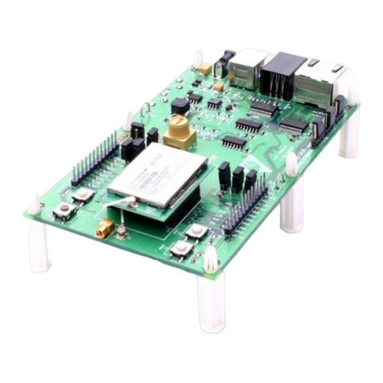
8.0 DNT90EDK Developer’s Kit Figure 8.0.1 shows the main contents of a DNT90EDK Developer’s kit: Figure 8.0.1 8.1 DNT90EDK Kit Contents Two DNT90EP radios installed in DNT90E interface boards (labeled Base and Remote) Two 9 V wall-plug power suppliers, 120/240 VAC, plus two 9 V batteries (not show above) ... -
Page 62: Developer's Kit Hardware Assembly
8.4 Developer’s Kit Hardware Assembly Observe ESD precautions when handling the kit circuit boards. When shipped, the DNT90EP radios and U.FL coax jumper cables are installed in the interface boards, as shown in Figure 8.4.1. If a DNT90EP ra- dio and/or the U.FL jumper cable has been unplugged after receipt, confirm the DNT90EP is correctly plugged into its interface board with the radio oriented so that its U.FL connector is next to the U.FL con- nector on the interface board, as shown in Figure 8.4.2. -
Page 63: Dnt90E Utility Program
There are three serial connectors and a power connector on the end of each interface board, as shown in Figure 8.4.4. The RJ-45 connector provides an RS232 interface to the DNT90EP’s main serial port. The USB connector provides an optional interface to the radio’s main serial port. The RJ-11 connector pro- vides an RS232 interface to the radio’s optional diagnostic port. -
Page 64: Initial Kit Operation
8.6 Initial Kit Operation Create a file folder on the PC and copy the contents of the kit CD into the folder. Connect the Base to the PC and power up the Base using a wall-plug power supply. The DNT90E Demo utility program is located in the PC Programs folder. The DNT90E Demo utility program requires no installation and can be simply copied to the PC and run. - Page 65 Click on Connect to open the Select Comm Port Settings dialog box, as shown in Figure 8.6.2. If necessary, set the baud rate to 9600 bps. Set the CommPort to match the serial port connected to the Base, either the hardware port or the USB virtual serial port. Then click OK to activate the serial connection.
- Page 66 MAC address in the MAC Address field under Radio 1 and then press the Enter key to display the Re- mote information. If any difficulty is encountered in setting up the DNT90EDK development kit, contact MURATA’s module tech- nical support group. The phone number is +1.678.684.2000. Phone support is available from 8:30 AM to 5:30 PM US Eastern Time Zone, Monday through Friday.
-
Page 67: Serial Communication And Radio Configuration
8.6.1 Serial Communication and Radio Configuration Connect PCs to both the Base and the Remote for serial communication testing (alternately one PC can be used with two serial ports and two instances of the DNT90E Demo program running). Click the Stop button under the Refresh Delay label on the I/O Tools tab and move to the Transmit Tools tab, as shown in Figure 8.6.1.1. - Page 68 Returning to the I/O Tools tab, the multi-tab Configuration window for each radio can be accessed by clicking on its Config button. The data presented on the first six tabs corresponds to configuration register Banks 0 through 5 as discussed in Section 4.2 above, with the data on the next two tabs corresponding to configuration register Bank 6.
- Page 69 Figure 8.6.1.3 Figure 8.6.1.3 shows the System tab contents, corresponding to Bank 1. The current values of each pa- rameter are displayed and can be updated by selecting from the drop-down menu or entering data from the keyboard, and then pressing the Apply Changes button. Note that Bank 1 holds configuration parame- ters for the base only except for Broadcast Mode, which applies to both the base and the remotes.
- Page 70 Figure 8.6.1.5 Figure 8.6.1.5 shows the Serial tab contents corresponding to the serial parameters in Bank 3. The val- ues shown are the defaults for serial port operation. Figure 8.6.1.6 Figure 8.6.1.6 shows the Protocol tab contents, corresponding to Bank 4. Transparent serial data com- munication is currently chosen.
- Page 71 Figure 8.6.1.7 Figure 8.6.1.7 shows the I/O Parameters tab contents, corresponding to Bank 5. All GPIO ports are con- figured as inputs. The 12-bit ADC input readings and DAC output settings are given in Big-Endian byte order. Event flags are presented on the right side of the window. Figure 8.6.1.8 Figure 8.6.1.8 shows the first I/O Settings tab contents, corresponding to Bank 6 GPIO configurations other than alternate GPIO functions.
- Page 72 Figure 8.6.1.9 Figure 8.6.1.9 shows the second I/O Setup tab contents, corresponding to Bank 6 ADC input and DAC output parameters. The ADC and DAC reference voltages, the ADC sampling interval, the high and low ADC thresholds for event reporting and event reporting triggers on each ADC channel can be set, along with the initial output values for each DAC channel.
-
Page 73: Dnt90E Interface Board Features
8.7 DNT90E Interface Board Features The locations of the LEDs on the interface board that are used by the DNT90E are shown in Figure 8.8.1. Figure 8.8.1 DCD LED, D11, illuminates on a router or remote to indicate it is registered with its parent and can partic- ipate in RF communications. - Page 74 ware to be installed with a terminal program that supports YMODEM. The boot loader is activated with a shorting plug on JP13. Pin strip J6 provides access to various DNT90E pins as shown on the silkscreen. Pressing switch SW3 will reset the DNT90EP. Switch S4 is not used with the DNT90E. Figure 8.8.3 Figure 8.8.3 shows the connectors to the left of the DNT90EP mounting socket.
-
Page 75: Troubleshooting
9.0 Troubleshooting DNT90E not responding - make sure /RESET is not asserted (logic low). Make sure the host serial port settings match the DNT90E serial port settings. Can not enter protocol mode - make sure the host data rate is correct. The DNT90E defaults to 9.6 kbps. If using the EnterProtocolMode command, send the complete protocol format for this command. -
Page 76: Appendices
10.1 Ordering Information DNT90EC: transceiver module for solder-pad mounting DNT90EP: transceiver module for pin-socket mounting 10.2 Technical Support For DNT90E technical support call MURATA at (678) 684-2000 between the hours of 8:30 AM and 5:30 PM Eastern Time www.RFM.com Technical support +1.678.684.2000 Page 74 of 80 ©... -
Page 77: Dnt90E Mechanical Specifications
10.3 DNT90E Mechanical Specifications D N T 9 0 C O u t l i n e a n d M o u n t i n g D e n s i o n s 1 . 4 5 0 ( 3 6 . - Page 78 D N T 9 0 P O u t l i n e a n d M o u n t i n g D i m e n s i o n s 1 . 4 5 0 ( 3 6 . 8 ) 0 .
-
Page 79: Dnt90E Development Board Schematic
10.4 DNT90E Development Board Schematic www.RFM.com Technical support +1.678.684.2000 Page 77 of 80 © 2010-2012 by RF Monolithics, Inc. E-mail: tech_sup@rfm.com DNT90 Integration Guide - 08/09/12... - Page 80 www.RFM.com Technical support +1.678.684.2000 Page 78 of 80 © 2010-2012 by RF Monolithics, Inc. E-mail: tech_sup@rfm.com DNT90 Integration Guide - 08/09/12...
- Page 81 www.RFM.com Technical support +1.678.684.2000 Page 79 of 80 © 2010-2012 by RF Monolithics, Inc. E-mail: tech_sup@rfm.com DNT90 Integration Guide - 08/09/12...
-
Page 82: Warranty
11.0 Warranty Seller warrants solely to Buyer that the goods delivered hereunder shall be free from defects in materials and workmanship, when given normal, proper and intended usage, for twelve (12) months from the date of delivery to Buyer. Seller agrees to repair or replace at its option and without cost to Buyer all defective goods sold hereunder, provided that Buyer has given Seller written notice of such warranty claim within such warranty period.
Need help?
Do you have a question about the DNT90E Series and is the answer not in the manual?
Questions and answers