Table of Contents
Advertisement
Quick Links
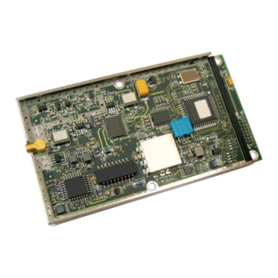
WIT2420
2.4GHz Spread Spectrum
Wireless Industrial Transceiver
Integration Guide
nd
June 2
2021
Note:
This unit has been tested and found to
comply with the limits for a class A digital device,
pursuant to part 15 of the FCC Rules.
These
limits
are
designed
to
provide
reasonable
protection against harmful interference when the
equipment
is
operated
in
a
commercial
environment.
This equipment generates, uses,
and can radiate radio frequency energy and, if not
installed and used in accordance with the
instruction
manual,
may
cause
harmful
interference to radio communications. Operation
of this equipment in a residential area is likely to
cause harmful interference in which case the user
will be required to correct the interference at his
own expense.
Advertisement
Table of Contents

Related Manuals for Murata WIT2420


Summary of Contents for Murata WIT2420
- Page 1 WIT2420 2.4GHz Spread Spectrum Wireless Industrial Transceiver Integration Guide June 2 2021 Note: This unit has been tested and found to comply with the limits for a class A digital device, pursuant to part 15 of the FCC Rules. These...
- Page 2 The final host product still requires Part 15 Subpart B compliance testing with the modular transmitter installed. If the WIT2420 is installed within another device the outside of the device into which the WIT2420 is installed must also display a label referring to the enclosed module. The label required for the WIT2420 module is as follows: Contains FCC ID: HSW-2420 and Contains IC: 4492A-2420.
-
Page 3: Table Of Contents
5.3. Protocol Commands ............................ 21 5.4. Status Commands ............................24 5.5. Memory Commands ............................ 25 5.6. Modem Command Summary ........................26 6. WIT2420 DEVELOPER’S KIT ..........................27 6.1. COM24/WinCOM24 ............................ 27 6.2. Demonstration Procedure ........................... 28 6.3. Troubleshooting ............................29 7. -
Page 4: Introduction
1. INTRODUCTION The WIT2420 radio transceiver provides reliable wireless connectivity for either point-to-point or multipoint applications. Frequency hopping spread spectrum technology ensures maximum resistance to noise and multipath fading and robustness in the presence of interfering signals, while operation in the 2.4GHz ISM band allows license-free use and worldwide compliance. -
Page 5: Frequency Hopping Vs. Direct Sequence
Transmitting the data signal as usual, but varying the carrier frequency rapidly according to a pseudo-random pattern over a broad range of channels produces a frequency hopping spectrum system. 6/2/2021 Murata Electronics Corporation... - Page 6 (including the U.S.) for the purpose of allowing compliant spread spectrum systems to operate freely without the requirement of a site license. This regulatory convenience alone has been a large motivation for the industry-wide move toward spread spectrum. 6/2/2021 Murata Electronics Corporation...
-
Page 7: Radio Operation
The data transmit delay parameter allows for the transmission of groups of continuous data in transparent mode (protocol mode 0). The amount of data that 6/2/2021 Murata Electronics Corporation... -
Page 8: Data Transmission
Commands for complete details on parameters affecting the transmission of data. 2.2. Data Transmission The WIT2420 supports two network configurations: point-to-point and point-to-multipoint. In a point-to-point network, one radio is set up as the base station and the other radio is set up as a remote. -
Page 9: Point-To-Multipoint
For applications needing guaranteed bandwidth availability, the TDMA mode of the WIT2420 can meet this requirement. In TDMA mode, each remote has an assigned time slot during which it can transmit. The base station time slot is set independently of the remote time slots through the Set Base Slot Size command. - Page 10 = 18 bytes of data per hop. 17.36s Note that the 18 bytes is the actual number of data bytes that can be sent. If the WIT2420 is using a protocol mode, the packet overhead does not need to be considered. So in this...
-
Page 11: Full Duplex Communication
WIT2420 can still communicate reliably. Data input to the WIT2420 is broken up by the radio into packets. A 24-bit checksum is attached to each packet to verify that it was correctly received. If the packet is received... -
Page 12: Modes Of Operation
2.3. Modes of Operation 2.3.1. Control and Data Modes The WIT2420 has two modes of operation: Control mode and Data mode. When in Control Mode, the various radio and modem parameters can be modified. When in Data Mode, only data can be transmitted. The default mode is Data Mode. There are two ways to enter Control Mode. -
Page 13: Low Power Mode And Duty Cycling
To compensate for the variations in nominal baud rates, the WIT2420 supports an RF flow control mode for point-to-point operation. In this mode, when the receive buffer of the receiving WIT2420 is close to full, the receiving WIT2420 stops acknowledging transmissions. -
Page 14: Protocol Modes
The remotes may still use transparent mode without formatting to send data to the base, if desired. The WIT2420 supports 10 protocol formats that are described in detail below. The protocol format is selected through the Set Protocol Mode command. - Page 15 CONNECT DISCONNECT mode 04 This is the packet format used by the WIT2400. This allows legacy software to operate the WIT2420. Note however, that since different air data rates are used, WIT2420s and WIT2400s cannot be mixed in a network.
-
Page 16: Packet Formats
The radio will not break up a packet over multiple hops. Packets with a data length greater than maximum data length will not be sent and will be discarded. This parameter is variable and depends on the number of remotes currently registered. 6/2/2021 Murata Electronics Corporation... -
Page 17: Connect Packet
1110 1001 11HH HHHH 0111 1111 : handle number (1-62) When a remote goes out of range or roams to another cell, the base issues a disconnect packet to indicate that the remote is no longer available. 6/2/2021 Murata Electronics Corporation... -
Page 18: Modem Interface
4. MODEM INTERFACE Electrical connection to the WIT2420 is made through a 16-pin male header on the modem module. The signals are 3.3 volt signals and form an RS-232 style asynchronous serial interface. The table below provides the connector pinout. -
Page 19: Interfacing To 5 Volt Systems
4.1. Interfacing to 5 Volt Systems The modem interface signals on the WIT2420 are 3.3 volt signals. To interface to 5 volt signals, the resistor divider network shown below must be placed between the 5 volt signal outputs and the WIT2420 signal inputs. The output voltage swing of the WIT2420 3.3 volt signals is sufficient to drive 5 volt logic inputs. -
Page 20: Power-On Reset Requirements
Section 2.2.3 TDMA Mode for the remote throughput calculation. 4.4 Power-On Reset Requirements The WIT2420 has an internal reset circuit that provides 100ms for power to the module to be applied and stabilized as well as removed. If the host cannot guarantee that power will be within the specified voltage range within 100ms of power being applied and be completely removed within 100ms of dropping below 3.3 volts, the host must apply a Reset signal to the... -
Page 21: Modem Commands
5. MODEM COMMANDS The WIT2420 is configured and controlled through a series of commands. These commands are sent to the modem directly when the modem is in Control Mode when the modem is in Data Mode if the escape sequence is enabled. The command syntax is the same for either method, a one- or two-letter command followed by one or more parameters. -
Page 22: Network Commands
When using a protocol mode, make sure to count in packet overhead when calculating network performance. Refer to the section on Protocol Modes for details on each format. 5.2. Network Commands Network commands are used to set up a WIT2420 network and to set radio addressing and configuration. Command... - Page 23 Set Transmit Power The WIT2420 has two preset transmit power levels, 10mW (10dBm) and 100mW (20dBm). Control of the transmit power is provided through this command. Default is 100mW.
-
Page 24: Protocol Commands
Set Hop Duration Sets the length of time the transceiver spends on each frequency channel. A smaller value will allow the remote to lock on to the base signal faster at system startup, and will generally 6/2/2021 Murata Electronics Corporation... - Page 25 When a host is sending a group of data that needs to be sent together, setting this parameter will provide time for the group of data to be sent by the host before the radio transmits. If the 6/2/2021 Murata Electronics Corporation...
- Page 26 When redundant transmit mode is used, receiving radios will discard all subsequent retransmissions once the transmission has been successfully received. Thus the receiving host will receive just one copy of the transmission. 6/2/2021 Murata Electronics Corporation...
-
Page 27: Status Commands
5.4. Status Commands These commands deal with general interface aspects of the operation of the WIT2420. Command Description zb[?|0|1] Banner Display Disable 0 = disabled 1 = enabled (default) zc[?|0..2] Set Escape Sequence Mode 0 = disabled 1 = once after reset (default) 2 = unlimited times Read factory serial number high byte. -
Page 28: Memory Commands
Store Memory Recall Factory Defaults Resets the WIT2420 to its factory default state. This is useful for testing purposes or if there is a problem in operation of the system and the configuration is suspect. Use the Store Memory command afterwards if you wish the factory default settings to be remembered the next time you cycle power or reset the radio. -
Page 29: Modem Command Summary
Note: Brackets ([,]) as used here denote a set of optional arguments. Vertical slashes separate selections. For example, given the string wn[?|00..3f], legal commands would be wn?, wn0, wn3, and wn2a. Most commands which set a parameter also have a ? option which displays the current parameter setting; e.g., wn?. 6/2/2021 Murata Electronics Corporation... -
Page 30: Wit2420 Developer's Kit
The pinout is provided in Section 7.3. The modems can be used with just a three wire connection. Transmit data, receive data and ground are the three required connections. Note that in this configuration, no flow control is available as the WIT2420 does not support software flow control. -
Page 31: Demonstration Procedure
Sets data rate of PC serial port to next higher value. Value is displayed in PgUp status line. Useful when COM24 is used to change the WIT2420 interface data rate. COM24 can communicate at new data rate without having to exit and re-enter COM24. -
Page 32: Troubleshooting
Can’t enter modem control mode. Make sure the host data rate is correct. The WIT2420 defaults to 9600 bps asynchronous. Evaluation units do not have external access to the CFG_SEL signal; you must use the :WIT2420 power-on escape sequence to access modem control mode. - Page 33 Make sure DTR and RTS are asserted. DSR should be on to indicate the radio is ready. OEM Module is in an unknown state. Use the command to restore the factory defaults. Note that the serial baud rate must be known for the module to receive this command. 6/2/2021 Murata Electronics Corporation...
-
Page 34: Appendices
(refer to section 7.6 for mechanical drawing) RF Connector: Huber/Suhner: 85 MMCX 50-0-1 Mating Huber/Suhner: 11 MMCX-50-2-3 (straight) Huber/Suhner: 16 MMCX-50-2-2 (rt. angle) Data/Power Connector: Samtec: DIS5-108-51-L-D Mating Samtec: CLP-108-02-G-D (PCB mount) Samtec: FFSD-08 (IDC cable) 6/2/2021 Murata Electronics Corporation... -
Page 35: Serial Connector Pinouts
The HN-510 can operate with just these three wires connected. However, as the WIT2420 does not support software flow control, there will be no flow control in this mode. If the DCE device fails to respond, connect DCD from the HN-510 to the DTR and RTS inputs to activate the DCE device whenever the WIT2420 asserts carrier. -
Page 36: Reference Design
WIT2410 Interface R1OUTB TXD_ 3.3V R1OUT R1IN DTR_SLEEP_ 3.3V R2OUT R2IN R3OUT R3IN RTS_3.3V VCC 3.3V FORCEO N If using a 5.0V converter use the following circuit for TXD,DTR,RTS FORCEO FF INVALID MAX3238 TXD_ 5V TXD_ 3.3V 6/2/2021 Murata Electronics Corporation... - Page 37 6/2/2021 Murata Electronics Corporation...
Need help?
Do you have a question about the WIT2420 and is the answer not in the manual?
Questions and answers