Table of Contents
Advertisement
Quick Links
Revision History
Revision
Date
1.0
10/19/11
2.0
10/27/14
©2009-2014 by Murata Electronics N.A., Inc.
DNT24 Integration Guide R2.0 - 10/27/14
Author
Change Description
F. Perkins
Initial Issue
R. Willett
Reformatted for new Murata V.I.
www.murata.com
RFM products are now
Murata products.
DNT24 Series
2.4 GHz
Spread Spectrum
Wireless Transceivers
Integration Guide
Advertisement
Table of Contents

Related Manuals for Murata DNT24 Series


Summary of Contents for Murata DNT24 Series
- Page 1 2.4 GHz Spread Spectrum Wireless Transceivers Integration Guide Revision History Revision Date Author Change Description 10/19/11 F. Perkins Initial Issue 10/27/14 R. Willett Reformatted for new Murata V.I. ©2009-2014 by Murata Electronics N.A., Inc. DNT24 Integration Guide R2.0 - 10/27/14 www.murata.com...
- Page 2 Model Number Gain Impedance Omnidirectional OD12-2400 12 dBi 50 ohm Corner SCR14-2400CT 14 dBi 50 ohm Patch PA2412 12 dBi 50 ohm Chip FR05-S1-N-0-102 1.7 dBi 50 ohm ©2009-2014 by Murata Electronics N.A., Inc. DNT24 Integration Guide R2.0 - 10/27/14 www.murata.com...
- Page 3 See Section 6.8 of this manual for regulatory notices and labeling requirements. Changes or modifications to a DNT24 not expressly approved by MURATA may void the user’s authority to operate the module. ©2009-2014 by Murata Electronics N.A., Inc. DNT24 Integration Guide R2.0 - 10/27/14...
-
Page 4: Table Of Contents
Configuring the SPI Port ......................24 Configuring Digital I/O ......................25 Configuring Analog I/O ......................25 Configuring I/O Event Reporting and I/O Binding ..............26 Configuring Sleep Mode ......................27 ©2009-2014 by Murata Electronics N.A., Inc. DNT24 Integration Guide R2.0 - 10/27/14 www.murata.com... - Page 5 Developer’s Kit Default Operating Configuration ..............61 Developer’s Kit Hardware Assembly ..................62 Utility Program ........................63 Initial Kit Operation......................... 63 8.6.1 Serial Communication and Radio Configuration .............. 66 ©2009-2014 by Murata Electronics N.A., Inc. DNT24 Integration Guide R2.0 - 10/27/14 www.murata.com...
- Page 6 10.1 Ordering Information ......................76 10.2 Technical Support ........................76 10.3 DNT24 Mechanical Specifications ..................77 10.4 DNT24 Development Board Schematic ................. 81 11.0 Warranty ........................... 84 ©2009-2014 by Murata Electronics N.A., Inc. DNT24 Integration Guide R2.0 - 10/27/14 www.murata.com...
-
Page 7: Dnt24 Introduction
This allows the signal to be reconstructed even though part of it may be lost or corrupted in transmission. ©2009-2014 by Murata Electronics N.A., Inc. DNT24 Integration Guide R2.0 - 10/27/14... -
Page 8: Frequency Hopping Versus Direct Sequence
Forms of spread spectrum - direct sequence and frequency hopping Figure 1.1.2 ©2009-2014 by Murata Electronics N.A., Inc. DNT24 Integration Guide R2.0 - 10/27/14 www.murata.com... -
Page 9: Dnt24 System Overview
2.1.1. This system consists of a base and one remote forming a single network. Point-to-point systems are often used to replace wired serial connections. Point-to-point systems are also used to transmit switch positions or analog signals from one location to another. Figure 2.1.1 ©2009-2014 by Murata Electronics N.A., Inc. DNT24 Integration Guide R2.0 - 10/27/14 www.murata.com... -
Page 10: Point-To-Multipoint Systems
The trade-off in store-and-forward systems is longer delivery times due to receiving and retransmitting a message several times. Store-and-forward systems are especially useful in applications such as agriculture where data is only col- lected periodically. ©2009-2014 by Murata Electronics N.A., Inc. DNT24 Integration Guide R2.0 - 10/27/14 www.murata.com... -
Page 11: Rf Channel Access
©2009-2014 by Murata Electronics N.A., Inc. DNT24 Integration Guide R2.0 - 10/27/14 www.murata.com... -
Page 12: Dnt24 Addressing
DNT24 system. ©2009-2014 by Murata Electronics N.A., Inc. DNT24 Integration Guide R2.0 - 10/27/14... -
Page 13: Fast Linking Techniques
Protocol-formatted messages are discussed in detail in Section 7. Briefly, protocol-formatted messages include a start-of- messages character, message length and message type information, the destination address of the message, and the message payload. ©2009-2014 by Murata Electronics N.A., Inc. DNT24 Integration Guide R2.0 - 10/27/14 www.murata.com... -
Page 14: Dnt24 Application Interfaces
The DNT24 SPI port can run at three clock rates in master mode - 125, 250 or 500 kbps. There are two message sources available to a DNT24 SPI master, a protocol-formatted RxData message or a stored command. The DNT24 master will ©2009-2014 by Murata Electronics N.A., Inc. DNT24 Integration Guide R2.0 - 10/27/14... - Page 15 50 bytes, provided the interval from the end of one burst to the start of the next burst is at least 2 ms, and the host suspends clocking on a low-to-high transition on /HOST_CTS. See Figure 3.2.4 Figure 3.2.3 ©2009-2014 by Murata Electronics N.A., Inc. DNT24 Integration Guide R2.0 - 10/27/14 www.murata.com...
- Page 16 See Section 5.2 for recommendations on configuring the SPI port, and Section 7.4.4 for detailed information on SPI port configuration parameters. Figure 3.2.5 ©2009-2014 by Murata Electronics N.A., Inc. DNT24 Integration Guide R2.0 - 10/27/14 www.murata.com...
-
Page 17: Digital I/O
2.7 V will be present. See Section 5.4 for recommendations on configuring the analog I/O, and Sections 7.4.6 and 7.4.7 for detailed information on analog I/O parameters. ©2009-2014 by Murata Electronics N.A., Inc. DNT24 Integration Guide R2.0 - 10/27/14 www.murata.com... -
Page 18: I/O Event Reporting And I/O Binding
Section 7.4 of this guide. Sections 4.2 through 5.7 discuss which parameters apply to various as- pects of configuring a DNT24 system, network or application interface. 4.2 Configuring a Basic Point-to-Point System ©2009-2014 by Murata Electronics N.A., Inc. DNT24 Integration Guide R2.0 - 10/27/14 www.murata.com... -
Page 19: Configuring A Basic Point-To-Multipoint Point System
Most applications will require only a few of these parameters be changed from their default values. But for those applications that need them, MURATA recommends the following configuration sequence. Skip the configuration steps where the default parameter value is satisfactory. - Page 20 The default is disabled. 14. Set the message retry limit on the base with the ArqAttemptLimit parameter in Bank 1. The default value is 6 re- tries. ©2009-2014 by Murata Electronics N.A., Inc. DNT24 Integration Guide R2.0 - 10/27/14 www.murata.com...
-
Page 21: Configuring A Store-And-Forward System
The maximum BSS is 105 bytes when a DNT24 system is configured for one slot. Adding additional slots reduces the maximum BSS by three bytes per slot. The BSS buffer is set nine bytes larger than ©2009-2014 by Murata Electronics N.A., Inc. DNT24 Integration Guide R2.0 - 10/27/14... - Page 22 RSS = 109 HD = 4*(80*109 + 2440) + 80*96 + 3280 HD = 44640 + 7680 + 3280 HD = 55600 round to 56000 µs = 56 ms ©2009-2014 by Murata Electronics N.A., Inc. DNT24 Integration Guide R2.0 - 10/27/14 www.murata.com...
-
Page 23: Dnt24 Application Interface Configuration
RS232/485 cable replacements, wireless sensor networks, wireless alarm systems and industrial remote control applications. Recommended configuration steps for each application interface are discussed in Sections 5.1 through 5.7 below. ©2009-2014 by Murata Electronics N.A., Inc. DNT24 Integration Guide R2.0 - 10/27/14 www.murata.com... -
Page 24: Configuring The Serial Port
Set the SPI master command string and string length by setting the SpiMasterCmdStr and SpiMas- terCmdLen parameters respectively in Bank 3. 3. Configure the edge trigger direction, bit-sampling edge and bit-order options by setting the SpiOptions parameter in Bank 3. ©2009-2014 by Murata Electronics N.A., Inc. DNT24 Integration Guide R2.0 - 10/27/14 www.murata.com... -
Page 25: Configuring Digital I/O
“0” high and low thresholds, and the ADC2 to ADC0 differential measurements is compared to the “1” high and low thresholds. In this case the “2” threshold values are not used. ©2009-2014 by Murata Electronics N.A., Inc. DNT24 Integration Guide R2.0 - 10/27/14... -
Page 26: Configuring I/O Event Reporting And I/O Binding
6. If I/O binding operation is desired, set the IoBindingEnable parameter in Bank 6 to 0x01. I/O binding is disabled by default, and cannot be used when the ADC is operating in differential mode. ©2009-2014 by Murata Electronics N.A., Inc. DNT24 Integration Guide R2.0 - 10/27/14 www.murata.com... -
Page 27: Configuring Sleep Mode
SPI message by setting the Wake-ResponseTime parame- ter. The default response time is 500 ms. Note that the setting of this parameter is overridden by some GpioEdgeTrig- ger parameter settings. ©2009-2014 by Murata Electronics N.A., Inc. DNT24 Integration Guide R2.0 - 10/27/14 www.murata.com... -
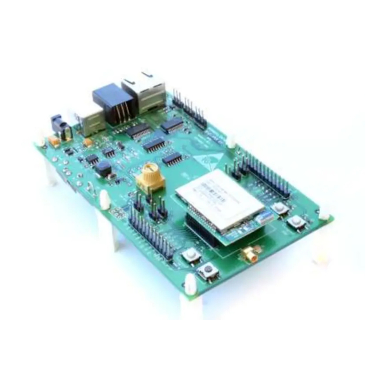
Page 28: Dnt24 Hardware
DNT24 Hardware Figure 6.0.1 The major components of the DNT24 series modules include a 2.4 GHz FHSS transceiver and a low current 8-bit microcontroller. The DNT24 modules operate in the 2.4 GHz MHz ISM band. There are 12 selectable hop- ping patterns providing compatibility with frequency allocations in most regions of the world. -
Page 29: Specifications
Average Operating Receive Current: Base or Remote, Continuous Data Stream Remote, Linked, No Data Sleep Current µA Operating Temperature Range Operating Relative Humidity Range (non condensing) Table 6.1.2 ©2009-2014 by Murata Electronics N.A., Inc. DNT24 Integration Guide R2.0 - 10/27/14 www.murata.com... -
Page 30: Module Pin Out
SPI clock signal. This pin is an output when operating as a master, and an input when operating as SCLK a slave. ©2009-2014 by Murata Electronics N.A., Inc. DNT24 Integration Guide R2.0 - 10/27/14 www.murata.com... -
Page 31: Antenna Connector
1.75 times the thickness of the circuit board. Note that other circuit board traces should be spaced away from the stripline to prevent signal coupling, as shown in Table 6.3.2. The stripline trace should be kept short to minimize its inser- tion loss. ©2009-2014 by Murata Electronics N.A., Inc. DNT24 Integration Guide R2.0 - 10/27/14 www.murata.com... -
Page 32: Power Supply And Input Voltages
Metal enclosures are not suitable for use with internal anten- nas as they will block antenna radiation and reception. Outdoor enclosures must be water tight, such as a NEMA 4X en- closure. ©2009-2014 by Murata Electronics N.A., Inc. DNT24 Integration Guide R2.0 - 10/27/14 www.murata.com... -
Page 33: Labeling And Notices
Contains IC: 4492A-DNT24 MURATA (Insert Model Designation DNT24C, DNT24CA, DNT24P or DNT24PA depending on the model used): This de- vice complies with Part 15 of the FCC Rules. Operation is subject to the following two conditions: (1) This device may not cause harmful interference, and (2) this device must accept any interference received, including interference that may cause undesired operation. -
Page 34: Dnt24 Protocol-Formatted Messages
Little-Endian byte order places the lowest order byte in the left-most byte of the argument and the highest order byte in the right-most byte of the argument. ©2009-2014 by Murata Electronics N.A., Inc. DNT24 Integration Guide R2.0 - 10/27/14... -
Page 35: Message Format Details
0xFB = Indicates start of protocol formatted message 0x01 Length 0x01 = Number of bytes in message following this byte 0x02 Packet Type 0x10 = EnterProtocolModeReply Table 7.3.3 ©2009-2014 by Murata Electronics N.A., Inc. DNT24 Integration Guide R2.0 - 10/27/14 www.murata.com... - Page 36 Register Bank Register bank number 0x05 Register Size Register size in bytes, only one parameter at a time (wrong register size will produce an error response) Table 7.3.7 ©2009-2014 by Murata Electronics N.A., Inc. DNT24 Integration Guide R2.0 - 10/27/14 www.murata.com...
- Page 37 Destination MAC address, in Little Endian byte order 0x06 - 0x72 Tx Data Up to 109 bytes of data to Base, or 105 bytes from Base Table 7.3.11 ©2009-2014 by Murata Electronics N.A., Inc. DNT24 Integration Guide R2.0 - 10/27/14 www.murata.com...
- Page 38 Register value, all bytes in the register (only one parameter at a time) *Bytes eight through the end of the message will not be returned in case of an error Table 7.3.14 ©2009-2014 by Murata Electronics N.A., Inc. DNT24 Integration Guide R2.0 - 10/27/14 www.murata.com...
- Page 39 Packet RX power in dBm, -128 to 126, or 127 if invalid 0x07 - 0x73 Rx Data Up to 105 bytes of data from Base, up to 109 bytes from Router or Remote Table 7.3.17 ©2009-2014 by Murata Electronics N.A., Inc. DNT24 Integration Guide R2.0 - 10/27/14 www.murata.com...
- Page 40 -128 to 126 or 127 if invalid RX power of packet as received by device’s parent in dBm, -128 to 126 or 0x0D Parent RX Power 127 if invalid Table 7.3.21 ©2009-2014 by Murata Electronics N.A., Inc. DNT24 Integration Guide R2.0 - 10/27/14 www.murata.com...
- Page 41 DAC0 setting, 0x0000 - 0x0FFF, in Little Endian byte order 0x12 - 0x13 DAC1 Setting DAC1 setting, 0x0000 - 0x0FFF, in Little Endian byte order Table 7.3.22 ©2009-2014 by Murata Electronics N.A., Inc. DNT24 Integration Guide R2.0 - 10/27/14 www.murata.com...
-
Page 42: Configuration Parameter Registers
MemorySave command to allow the change to persist through a reset or power cycle. A HopDuration change takes effect immediately. Child radios will re-link following a HopDuration parameter change as they receive the updated hop duration value from the base. ©2009-2014 by Murata Electronics N.A., Inc. DNT24 Integration Guide R2.0 - 10/27/14 www.murata.com... - Page 43 BaseModeNetID. The valid range of this parameter is 0x00 to 0x3F. A value greater than 0x3F is invalid and will be forced to 0x00 on a base. A router with an invalid Base-ModeNetID will be forced to operate as a remote. ©2009-2014 by Murata Electronics N.A., Inc. DNT24 Integration Guide R2.0 - 10/27/14...
- Page 44 BeaconCount register is already set to a non-zero value. It auto-clears on a base station and will read back as 0 after it is cleared. On a router or remote, it would do nothing and will not clear except after reset. ©2009-2014 by Murata Electronics N.A., Inc. DNT24 Integration Guide R2.0 - 10/27/14...
-
Page 45: Bank 0X01 - System Settings
5 channel band for fast linking, use in US and Canada only 0x0D 2415 - 2475 MHz 0xFF Auto Auto Autoscan for remote to match base Table 7.4.2.2 ©2009-2014 by Murata Electronics N.A., Inc. DNT24 Integration Guide R2.0 - 10/27/14 www.murata.com... - Page 46 LinkDropThreshold - this is the number of consecutive beacons missed by a remote that causes the remote to restart a link acquisition search. Please contact MURATA technical support before making changes to the pa- rameter.
-
Page 47: Bank 0X02 - Status Parameters
HarwareVersion - this parameter holds an identifier indicating the hardware revision (ASCII character). A value of 0x43 is defined for the DNT24 Revision C hardware. FirmwareVersion - this parameter holds the firmware version of the radio in 2-digit BCD format. ©2009-2014 by Murata Electronics N.A., Inc. DNT24 Integration Guide R2.0 - 10/27/14 www.murata.com... -
Page 48: Bank 0X03 - Serial And Spi Settings
0x03 9.6 kbps 0x04 14.4 kbps 0x05 19.2 kbps 0x06 28.8 kbps 0x07 38.4 kbps 0x08 57.6 kbps 0x09 115.2 kbps 0x0A 230.4 kbps 0x0B 250.0 kbps ©2009-2014 by Murata Electronics N.A., Inc. DNT24 Integration Guide R2.0 - 10/27/14 www.murata.com... -
Page 49: Bank 0X04 - Host Protocol Settings
0x01 0..255 0 (No timeout) 0x04 0x02 MinPacketLength 0x01 0..255 1 (byte) 0x04 0x03 TransPtToPtMode 0x01 0..1 1 (Last RX) 0x04 0x04 MsgsPerHop 0x01 1..8 Table 7.4.5.1 ©2009-2014 by Murata Electronics N.A., Inc. DNT24 Integration Guide R2.0 - 10/27/14 www.murata.com... -
Page 50: Bank 0X05 - I/O Parameters
All-IO - this 13-byte parameter packs all the following parameters into a single value. Note that the information in parame- ters GPIO0 through GPIO5 is compressed into a single byte to save space in the All-IO parameter. When the ADC is op- ©2009-2014 by Murata Electronics N.A., Inc. DNT24 Integration Guide R2.0 - 10/27/14... - Page 51 1 GPIO1 edge transition bit 0 GPIO0 edge transition Dac0 through Dac1 - sets the DAC outputs. The range of this parameter is 0x0000 to 0x0FFF. ©2009-2014 by Murata Electronics N.A., Inc. DNT24 Integration Guide R2.0 - 10/27/14 www.murata.com...
-
Page 52: Bank 0X06 - I/O Settings
0x02 0x8000 0x06 0x46 AdcDiffOffsetCh1 0x02 0x0000 FastAdcPrescaler 0x06 0x47 0x01 1 byte, range 1..7 5 (÷128) SlowAdcPresccaler 0x06 0x48 0x01 1 byte, range 0..7 2 (÷16) ©2009-2014 by Murata Electronics N.A., Inc. DNT24 Integration Guide R2.0 - 10/27/14 www.murata.com... - Page 53 This enables the user to provide alternate configurations during sleep that will help minimize current consumption. Bits 0..5 correspond to GPIO0..GPIO5. Setting a GpioSleepDir bit to 1 to specifies an output; 0 specifies an input. ©2009-2014 by Murata Electronics N.A., Inc. DNT24 Integration Guide R2.0 - 10/27/14 www.murata.com...
- Page 54 IoPreDelay - this parameter sets the time in milliseconds to delay collection of ADC readings after an event occurs, to al- low settling of ADC input voltages. ©2009-2014 by Murata Electronics N.A., Inc. DNT24 Integration Guide R2.0 - 10/27/14 www.murata.com...
- Page 55 Vcc/1.6. The scale factor parameter is multiplied by 32768. for example, the parameter value for a scale factor of 1.12 = 1.12 * 32768 = 36700.16 or 0x8F5C. ©2009-2014 by Murata Electronics N.A., Inc. DNT24 Integration Guide R2.0 - 10/27/14...
- Page 56 AdcDiffScaleFactorCh0/1 and AdcDiffOffsetCh0/1 - these parameters are applied to the raw ADC readings in differential mode. These values are not factory calibrated, but can be calibrated by the user. ©2009-2014 by Murata Electronics N.A., Inc. DNT24 Integration Guide R2.0 - 10/27/14...
-
Page 57: Bank 0Xff - Special Functions
9.6 kbps 0x04 14.4 kbps 0x05 19.2 kbps 0x06 28.8 kbps 0x07 38.4 kbps (default) 0x08 57.6 kbps 0x09 115.2 kbps 0x0A 230.4 kbps 0x0B 250.0 kbps ©2009-2014 by Murata Electronics N.A., Inc. DNT24 Integration Guide R2.0 - 10/27/14 www.murata.com... -
Page 58: Protocol-Formatted Message Examples
SetRemoteRegister commands. The command to set the IoReportInterval to 10 seconds is: Length PktType Lo MAC Hi MAC Bank Size Lo Val Hi Val 0xFB 0x0B 0x07 0x56 0x34 0x12 0x1C 0x06 0x04 0x10 0x27 0x00 0x00 ©2009-2014 by Murata Electronics N.A., Inc. DNT24 Integration Guide R2.0 - 10/27/14 www.murata.com... -
Page 59: Sensor Message
Endian format, 7B 08. The ADC reading is thus 0x087B (2171). The RSSI value is the byte following the address, 0xB7 (- 73 dBm). The TxStatus byte to the right of the GetRemoteRegisterReply Packet Type is 0x00, showing the packet was acknowledged on the RF channel. ©2009-2014 by Murata Electronics N.A., Inc. DNT24 Integration Guide R2.0 - 10/27/14 www.murata.com... -
Page 60: Event Message
If the remote is placed in periodic sleep mode (SleepMode = 1), a suitable value of the WakeResponseTime parame- ter should be set to allow the base application to analyze the I/O report and send back a command to the remote as needed. ©2009-2014 by Murata Electronics N.A., Inc. DNT24 Integration Guide R2.0 - 10/27/14 www.murata.com... -
Page 61: Dnt24Dk/Dnt24Adk Developer's Kits
9600 bps, 8N1. One DNT24 is preconfigured as a base and the other as a remote. Labels on the bottom of the interface boards specify Base or Remote. ©2009-2014 by Murata Electronics N.A., Inc. DNT24 Integration Guide R2.0 - 10/27/14... -
Page 62: Developer's Kit Hardware Assembly
3. If using a serial cable, connect the Base interface board to the PC using a RJ-45/DB-9F cable assembly (labels on the bottom of the interface boards specify Base or Remote). Then power the Base with a supplied wall-plug power supply. Continue at Step 5 below. ©2009-2014 by Murata Electronics N.A., Inc. DNT24 Integration Guide R2.0 - 10/27/14 www.murata.com... -
Page 63: Utility Program
PC and run. Figure 8.6.1 1. Start the Demo on the PC. The Demo program start-up window is shown in Figure 8.6.1. ©2009-2014 by Murata Electronics N.A., Inc. DNT24 Integration Guide R2.0 - 10/27/14 www.murata.com... - Page 64 5. Click on the drop-down box at the top of the Radio 1 column and click on the MAC Address (preloaded when the Remote is turned on after the Base), or load the MAC Address for the Remote from the heartbeat message. ©2009-2014 by Murata Electronics N.A., Inc. DNT24 Integration Guide R2.0 - 10/27/14...
- Page 65 Potentiometer (ADC0) data in the Local Radio column. If any difficulty is encountered in setting up the DNT24DK development kit, contact MURATA’s module technical support group. The phone number is +1.678.684.2000. Phone support is available from 8:30 AM to 5:30 PM US Eastern Time Zone, Monday through Friday.
-
Page 66: Serial Communication And Radio Configuration
When the Transmit Interval is set to a positive number, Pressing the Transmit button once will cause a transmission each transmit interval (seconds) until the button is pressed again. ©2009-2014 by Murata Electronics N.A., Inc. DNT24 Integration Guide R2.0 - 10/27/14... - Page 67 Apply Changes button. Note that data is displayed and entered in Big-Endian order. The utility program automatically reorders multi-byte data to and from Little-Endian order when building or interpreting messages. Figure 8.6.1.3 ©2009-2014 by Murata Electronics N.A., Inc. DNT24 Integration Guide R2.0 - 10/27/14 www.murata.com...
- Page 68 Figure 8.6.1.5 Figure 8.6.1.5 shows the Serial tab contents corresponding to the serial parameters in Bank 3. The values shown are the defaults for serial port operation. ©2009-2014 by Murata Electronics N.A., Inc. DNT24 Integration Guide R2.0 - 10/27/14 www.murata.com...
- Page 69 Figure 8.6.1.7 shows the I/O Parameters tab contents, corresponding to Bank 5. All GPIO ports are configured as inputs. The 12-bit ADC input readings and DAC output settings are given in Big-Endian byte order. Event flags are presented on the right side of the window. ©2009-2014 by Murata Electronics N.A., Inc. DNT24 Integration Guide R2.0 - 10/27/14 www.murata.com...
- Page 70 ADC channel can be set, along with the initial output values for each DAC channel. The event reporting I/O predelay and alternate GPIO functions can also be set from this tab. ©2009-2014 by Murata Electronics N.A., Inc. DNT24 Integration Guide R2.0 - 10/27/14...
- Page 71 Figure 8.6.1.10 shows the third I/O Setup tab contents, corresponding to Bank 6 ADC input and DAC output scaling, offset and related parameters. These parameters should not be changed from their defaults unless precision inputs are availa- ble to calibrate the ADC and DAC functions. ©2009-2014 by Murata Electronics N.A., Inc. DNT24 Integration Guide R2.0 - 10/27/14 www.murata.com...
- Page 72 The Demo Utility File, Options and Help menus are shown in Figure 8.6.1.11. Figure 8.6.1.11 ©2009-2014 by Murata Electronics N.A., Inc. DNT24 Integration Guide R2.0 - 10/27/14 www.murata.com...
-
Page 73: Interface Board Features
JP4 connects ADC1 to a thermistor temperature sensor. The DNT24 has its own boot loader utility that allows the protocol firmware to be installed with a terminal program that supports YMODEM. The ©2009-2014 by Murata Electronics N.A., Inc. DNT24 Integration Guide R2.0 - 10/27/14... - Page 74 9 V wall-plug power supply. Do not attempt to use the 9 V wall-plug power supply to power the DNT24P directly. The maximum allowed voltage input to the DNT24P is 5.5 V. ©2009-2014 by Murata Electronics N.A., Inc. DNT24 Integration Guide R2.0 - 10/27/14...
-
Page 75: Troubleshooting
<0 or 1> - For a router, this determines whether the stat option displays data associated with its operation as a base (1) or as a remote (0). ©2009-2014 by Murata Electronics N.A., Inc. DNT24 Integration Guide R2.0 - 10/27/14... -
Page 76: Appendices
DNT24PA: transceiver module for pin-socket mounting, includes on-board chip antenna 10.2 Technical Support For DNT24 technical support call MURATA at (678) 684-2000 between the hours of 8:30 AM and 5:30 PM Eastern Time ©2009-2014 by Murata Electronics N.A., Inc. DNT24 Integration Guide R2.0 - 10/27/14... -
Page 77: Dnt24 Mechanical Specifications
10.3 DNT24 Mechanical Specifications Figure 10.3.1 Figure 10.3.2 ©2009-2014 by Murata Electronics N.A., Inc. DNT24 Integration Guide R2.0 - 10/27/14 www.murata.com... - Page 78 Figure 10.3.3 Figure 10.3.4 ©2009-2014 by Murata Electronics N.A., Inc. DNT24 Integration Guide R2.0 - 10/27/14 www.murata.com...
- Page 79 Figure 10.3.2 ©2009-2014 by Murata Electronics N.A., Inc. DNT24 Integration Guide R2.0 - 10/27/14 www.murata.com...
- Page 80 Figure 10.3.3 ©2009-2014 by Murata Electronics N.A., Inc. DNT24 Integration Guide R2.0 - 10/27/14 www.murata.com...
-
Page 81: Dnt24 Development Board Schematic
10.4 DNT24 Development Board Schematic ©2009-2014 by Murata Electronics N.A., Inc. DNT24 Integration Guide R2.0 - 10/27/14 www.murata.com... - Page 82 ©2009-2014 by Murata Electronics N.A., Inc. DNT24 Integration Guide R2.0 - 10/27/14 www.murata.com...
- Page 83 ©2009-2014 by Murata Electronics N.A., Inc. DNT24 Integration Guide R2.0 - 10/27/14 www.murata.com...
-
Page 84: Warranty
SUPPLYING OF THE GOODS. THE FOREGOING WARRANTY EXTENDS TO BUYER ONLY AND SHALL NOT BE APPLICABLE TO ANY OTHER PERSON OR ENTITY INCLUDING, WITHOUT LIMITATION, CUSTOMERS OF BUYERS. Part # M-0024-0002, Rev F ©2009-2014 by Murata Electronics N.A., Inc. DNT24 Integration Guide R2.0 - 10/27/14 www.murata.com...
Need help?
Do you have a question about the DNT24 Series and is the answer not in the manual?
Questions and answers