
Subscribe to Our Youtube Channel
Related Manuals for Murata WIT910


Summary of Contents for Murata WIT910
- Page 1 WIT910 900 MHz Spread Spectrum Wireless Industrial Transceiver Integration ©2010-2015 by Murata Electronics N.A., Inc. WIT910 Integration guide (R) 05/14/15 www.murata.com...
- Page 2 Notice to users/installers using the 8.5 dBi Yagi antenna with the WIT910. FCC rules limit the use of this antenna, when connected to the WIT910 module, to point-to-point applications only. It is the responsibility of the installer to ensure that the system is prohibited...
-
Page 3: Table Of Contents
5.2 Network Commands ......................22 5.3 Protocol Commands......................24 5.4 Status Commands .......................27 5.5 Memory Commands ......................28 5.6 Modem Command Summary....................29 6. WIT910 DEVELOPER’S KIT ....................30 7. WinCOM...........................31 Starting the program ........................33 Function Keys ..........................36 WinCom Tools...........................37 ©2010-2015 by Murata Electronics N.A., Inc. - Page 4 8.1.4. Mechanical Specifications ..................44 8.2 Serial Connector Pinouts ....................45 8.3 Approved Antennas ......................45 8.4 Technical Support .......................46 8.5 Reference Design........................47 8.6 Mechanical Drawing – WIT910 ..................48 8.7 Warranty ..........................49 ©2010-2015 by Murata Electronics N.A., Inc. WIT910 Integration guide (R) 05/14/15 www.murata.com...
-
Page 5: Introduction
900MHz ISM band allows license-free use and worldwide compliance. Standard communication rates between the WIT910 and the host are supported between 2400bps and 115bps. Non-standard rates are supported as well. An on-board buffer and an error-correcting over-the-air protocol provide smooth data flow and simplify the task of integration with existing applications. -
Page 6: Frequency Hopping Vs. Direct Sequence
2 of 49 ©2010-2015 by Murata Electronics N.A., Inc. WIT910 Integration guide (R) 05/14/15 www.murata.com... - Page 7 3 of 49 ©2010-2015 by Murata Electronics N.A., Inc. WIT910 Integration guide (R) 05/14/15 www.murata.com...
-
Page 8: Radio Operation
(protocol mode ). The amount of data that the base station can transmit per hop is determined by the base slot 4 of 49 ©2010-2015 by Murata Electronics N.A., Inc. WIT910 Integration guide (R) 05/14/15 www.murata.com... -
Page 9: Data Transmission
2.2 Data Transmission The WIT910 supports two network configurations: point-to-point and point-to- multipoint. In a point-to-point network, one radio is set up as the base station and the other radio is set up as a remote. In a point-to-multipoint network, a star topology is used with the radio set up as a base station acting as the central communications point and all other radios in the network set up as remotes. -
Page 10: Point-To-Multipoint
The WIT910 has a point-to-point direct mode which fixes the remote radio’s handle at 30H. This mode is recommended for point-to-point applications, especially if the remote is likely to periodically leave and re-enter the coverage area of the base. -
Page 11: Tdma Operation
For applications needing guaranteed bandwidth availability, the TDMA operation of the WIT910 can meet this requirement. In the WIT910 TDMA scheme, each remote has an assigned time slot during which it can transmit. The base station time slot is set independently of the remote time slots through the Set Base Slot Size command. - Page 12 = 47 bytes of data per hop. 46.3µs us However, the WIT910 sends data in groups of 4 bytes. Thus, each remote will be able to send 44 bytes of data. Note that the 44 bytes is the actual number of data bytes that can be sent.
-
Page 13: Full Duplex Communication
WIT910 can still communicate reliably. Data input to the WIT910 is broken up by the radio into packets. A 24-bit checksum is attached to each packet to verify that it was correctly received. If the packet is received... -
Page 14: Modes Of Operation
2.3 Modes of Operation 2.3.1. Control and Data Modes The WIT910 has two modes of operation: Control mode and Data mode. When in Control Mode, the various radio and modem parameters can be modified. When in Data Mode, only data can be transmitted. The default mode is Data Mode. There are two ways to enter Control Mode. -
Page 15: Low Power Mode And Duty Cycling
During this scanning the radio can consume up to 70 mA of current at 3.3-volts. The WIT910 employs a switching regulator so the current consumption will be less at higher voltages. -
Page 16: Protocol Modes
The remotes may still use transparent mode without formatting to send data to the base, if desired. The WIT910 supports 10 protocol formats that are described in detail below. The protocol format is selected through the Set Protocol Mode command. - Page 17 This mode sends data transparently but supports protocol mode 1 during reception. mode This mode sends data transparently but supports protocol mode 2 during reception. 13 of 49 ©2010-2015 by Murata Electronics N.A., Inc. WIT910 Integration guide (R) 05/14/15 www.murata.com...
-
Page 18: Data Packet
Acknowledgment requests are not supported for broadcasts. For this reason, it is a good idea to send broadcast messages several times to increase the odds of reaching all remotes. 14 of 49 ©2010-2015 by Murata Electronics N.A., Inc. WIT910 Integration guide (R) 05/14/15 www.murata.com... -
Page 19: Connect Packet
When a remote goes out of range or roams to another cell, the base issues a disconnect packet to indicate that the remote is no longer available. 15 of 49 ©2010-2015 by Murata Electronics N.A., Inc. WIT910 Integration guide (R) 05/14/15 www.murata.com... -
Page 20: Modem Interface
WIT910 4. MODEM INTERFACE Electrical connection to the WIT910 is made through a 16-pin male header on the modem module. The signals are 3.3-volt signals and form an RS-232 style asynchronous serial interface. The table below provides the connector pinout. -
Page 21: Interfacing To 5-Volt Systems
4.3 Three Wire Operation The WIT910 can be operated in a three wire configuration using just TxD, RxD and Ground. To operate the WIT910 in this configuration, the Sleep and RTS signals must be tied to ground. These signals are pulled up on the WIT910 module and if left disconnected will put the radio into sleep mode and RTS will be deasserted. -
Page 22: Power-On Reset Requirements
4.4 Power-On Reset Requirements The WIT910 has an internal reset circuit that generates and maintains the WIT910 in a reset state until the power supply voltage reaches a minimum of 2.5-volts for 100 milliseconds. This reset circuit protects the radio and non-volatile memory from brown- out voltage conditions. -
Page 23: Received Signal Strength Indicator
RSSI line needs to be buffered. This line cannot be connected to a sample and hold circuit directly. A simple buffer circuit will suffice. 19 of 49 ©2010-2015 by Murata Electronics N.A., Inc. WIT910 Integration guide (R) 05/14/15 www.murata.com... -
Page 24: Modem Commands
WIT910 5. MODEM COMMANDS The WIT910 is configured and controlled through a series of commands. These commands are sent to the modem directly when the modem is in Control Mode when the modem is in Data Mode if the escape sequence is enabled. The command syntax is the same for either method, a one- or two-letter command followed by one or more parameters. - Page 25 If an error is made in the baud rate setting toggling DTR or cycling power to the WIT910 will cause the previous baud rate to be used. Set Protocol Mode Enables the base station to operate in a multipoint network. Depending on the user application, more or less acknowledgment may be desired by the application.
-
Page 26: Network Commands
WIT910 5.2 Network Commands Network commands are used to set up a WIT910 network and to set radio addressing and configuration. Command Description wb[?|0|1] Set Transceiver Mode 0 = remote (default) 1 = base station wd[?|0-3f] Set Default Handle Used to override automatic handle assignment by the base station... - Page 27 Set Hopping Pattern The WIT910 has 32 preprogrammed hopping patterns (also referred to as network numbers). By using different hopping patterns, nearby or co-located networks can avoid interfering with each other’s transmissions. Even if both networks tried to use the same frequency, on the next hop they would be at different frequencies.
-
Page 28: Protocol Commands
25ms. The maximum value of is 47.02ms. For best results, do not specify a duration of less than 15 ms. 24 of 49 ©2010-2015 by Murata Electronics N.A., Inc. WIT910 Integration guide (R) 05/14/15 www.murata.com... - Page 29 The length of time the radio will wait is equal to the specified value times the hop duration. 25 of 49 ©2010-2015 by Murata Electronics N.A., Inc. WIT910 Integration guide (R) 05/14/15 www.murata.com...
- Page 30 When redundant transmit mode is used, receiving radios will discard all subsequent retransmissions once the transmission has been successfully received. Thus the receiving host will receive just one copy of the transmission. 26 of 49 ©2010-2015 by Murata Electronics N.A., Inc. WIT910 Integration guide (R) 05/14/15 www.murata.com...
-
Page 31: Status Commands
WIT910 5.4 Status Commands These commands deal with general interface aspects of the operation of the WIT910. Command Description zb[?|0|1] Banner Display Disable 0 = disabled 1 = enabled (default) zc[?|0..2] Set Escape Sequence Mode 0 = disabled 1 = once after reset 2 = unlimited times (default) Read factory serial number high byte. -
Page 32: Memory Commands
Display Modified Parameters Recall Factory Defaults Resets the WIT910 to its factory default state. This is useful for testing purposes or if there is a problem in operation of the system and the configuration is suspect. Use the Store Memory command afterwards if you wish the factory default settings to be remembered the next time you cycle power or reset the radio. -
Page 33: Modem Command Summary
For example, given the string wn[?|00..3f], legal commands would be wn?, wn0, wn3, and wn2a. Most commands which set a parameter also have a ? option which displays the current parameter setting; e.g., wn?. 29 of 49 ©2010-2015 by Murata Electronics N.A., Inc. WIT910 Integration guide (R) 05/14/15 www.murata.com... -
Page 34: Wit910 Developer's Kit
The pinout is provided in Section 7.2. The modems can be used with just a three wire connection. Transmit data, receive data and ground are the three required connections. Note that in this configuration, no flow control is available as the WIT910 does not support software flow control. -
Page 35: Wincom
Software Tools directory on the Manuals and Software CD and double- click on wincom2.1.exe follow the installation wizard. Once it has installed, open WinCOM by double-clicking on the WinCOM icon on the desktop. 31 of 49 ©2010-2015 by Murata Electronics N.A., Inc. WIT910 Integration guide (R) 05/14/15 www.murata.com... - Page 36 The Help menu displays the About screen which lists the version number, hardware and software information for the system being used. 32 of 49 ©2010-2015 by Murata Electronics N.A., Inc. WIT910 Integration guide (R) 05/14/15 www.murata.com...
-
Page 37: Starting The Program
Unless the “Echo” box is checked the typed data will not be displayed in the WinCOM window of the sending radio. 33 of 49 ©2010-2015 by Murata Electronics N.A., Inc. WIT910 Integration guide (R) 05/14/15 www.murata.com... - Page 38 When the radio is linked to another radio, a communications test can be run by clicking on the Transmit button or pressing the F6 key. Whatever ASCII string is in the Transmit String window will be transmitted as shown below. 34 of 49 ©2010-2015 by Murata Electronics N.A., Inc. WIT910 Integration guide (R) 05/14/15 www.murata.com...
- Page 39 The Clear Screen button deletes all the text in the display window. The Clear CTS and Clear DCD buttons reset the respective changes counters to zero. 35 of 49 ©2010-2015 by Murata Electronics N.A., Inc. WIT910 Integration guide (R) 05/14/15 www.murata.com...
-
Page 40: Function Keys
WinCOM can communicate at new data rate without having to exit and re-enter WinCOM. Sets data rate of PC serial port to next lower value. Value is displayed in PgDn status line. 36 of 49 ©2010-2015 by Murata Electronics N.A., Inc. WIT910 Integration guide (R) 05/14/15 www.murata.com... -
Page 41: Wincom Tools
The third allows for checking of available Comm Ports and is useful for refreshing the list. The fourth, Transmit Tools allows for testing of the Transparent, WIT2410/WIT910 or WIT2411 settings. Parameters related to how the transmission will take place can be set... - Page 42 The Packet Builder is an easy way to test the multipoint addressing mode of the WIT241x and WIT910 radios. Since the WIT241x and WIT910 radios operate in a star configuration in multipoint mode, only the base radio needs to address data to specific remotes.
-
Page 43: Script Commands
Asserts RTS De-asserts RTS Sends configuration escape sequence Obey CTS/RTS Do not obey CTS/RTS sc <cmd(arg)> Send WIT910 format configuration command wt <arg> Pause for arg milliseconds An example script file is shown below: br 115200 wt 200 wt 200... - Page 44 Finally, the eighth tool is Save to File which launches a Save As dialog that allows any data received to be loaded into a file. 40 of 49 ©2010-2015 by Murata Electronics N.A., Inc. WIT910 Integration guide (R) 05/14/15 www.murata.com...
-
Page 45: Demonstration Procedure
WIT910 Demonstration Procedure The procedure below provides a quick demonstration of the WIT910. 1. Attach a transceiver to each computer, preferably between 5' and 30' apart for convenience. 2. Start WinCOM running on both computers If you prefer, almost any other serial communications program such as Procomm or QModem set for 9600 bps will also work. -
Page 46: Troubleshooting
Can’t enter modem control mode. Make sure the host data rate is correct. The WIT910 defaults to 9600 bps asynchronous. Evaluation units do not have external access to the CFG_SEL signal; you must use the :wit2410 power-on escape sequence to access modem control mode. - Page 47 OEM Module is in an unknown state. Use the command to restore the factory defaults. Note that the serial baud rate must be known for the module to receive this command. 43 of 49 ©2010-2015 by Murata Electronics N.A., Inc. WIT910 Integration guide (R) 05/14/15 www.murata.com...
-
Page 48: Appendices
Huber/Suhner: 85 MMCX 50-0-1 Mating Huber/Suhner: 11 MMCX-50-2-3 (straight) Huber/Suhner: 16 MMCX-50-2-2 (rt. angle) Data/Power Connector: Samtec: DIS5-108-51-L-D Mating Samtec: CLP-108-02-G-D (PCB mount) Samtec: FFSD-08 (IDC cable) 44 of 49 ©2010-2015 by Murata Electronics N.A., Inc. WIT910 Integration guide (R) 05/14/15 www.murata.com... -
Page 49: Serial Connector Pinouts
SLEEP) are terminated for proper operation. 8.3 Approved Antennas The WIT910 is designed to ensure that no antenna other than the one fitted shall be used with the device. The end user must permanently affix the antenna by using an adhesive on the coupling such as Loctite, or ensure the antenna has a unique coupling. -
Page 50: Technical Support
WIT910 8.4 Technical Support For technical support call Murata™ at (678) 684-2004 between the hours of 8:30AM and 5:30PM Eastern Time. 46 of 49 ©2010-2015 by Murata Electronics N.A., Inc. WIT910 Integration guide (R) 05/14/15 www.murata.com... -
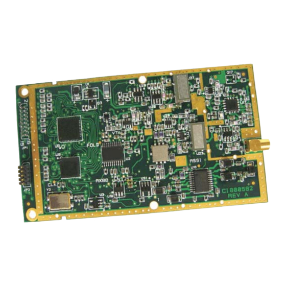
Page 51: Reference Design
WIT910 8.5 Reference Design 47 of 49 ©2010-2015 by Murata Electronics N.A., Inc. WIT910 Integration guide (R) 05/14/15 www.murata.com 2200 4300... -
Page 52: Mechanical Drawing - Wit910
WIT910 8.6 Mechanical Drawing – WIT910 48 of 49 ©2010-2015 by Murata Electronics N.A., Inc. WIT910 Integration guide (R) 05/14/15 www.murata.com... -
Page 53: Warranty
SUPPLYING OF THE GOODS. THE FOREGOING WARRANTY EXTENDS TO BUYER ONLY AND SHALL NOT BE APPLICABLE TO ANY OTHER PERSON OR ENTITY INCLUDING, WITHOUT LIMITATION, CUSTOMERS OF BUYERS. 49 of 49 ©2010-2015 by Murata Electronics N.A., Inc. WIT910 Integration guide (R) 05/14/15 www.murata.com... - Page 54 Mouser Electronics Authorized Distributor Click to View Pricing, Inventory, Delivery & Lifecycle Information: Murata OMNI092...
Need help?
Do you have a question about the WIT910 and is the answer not in the manual?
Questions and answers