Table of Contents
Advertisement
Quick Links
Advertisement
Table of Contents

Related Manuals for Anaheim Automation MDC300-240081 Series


Summary of Contents for Anaheim Automation MDC300-240081 Series
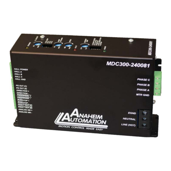
- Page 1 MDC300-240081 Series 220VAC, 7.5A Brushless Controller User’s Guide A N A H E I M A U T O M A T I O N 4985 E. Landon Drive Anaheim, CA 92807 (714) 992-6990 fax: (714) 992-0471 e-mail: info@anaheimautomation.com website: www.anaheimautomation.com...
-
Page 2: General Description
MDC300-240081 Driver Features • Peak Current Limit Setting from 2.5 to 7.5 Amps • Internal/External Potentiometer or Voltage Input Speed Control • On-board Potentiometer Ramp Up Adjustment • Single Input Speed and Direction Control (Auto-Direction) • 2-Quadrant Operation • Hall Sensor Feedback •... - Page 3 Pin Descriptions The inputs on the MDC300-240081 are optically isolated with the anode (+) and cathode (-) both brought out to the user. With no current going through the Direction, Freewheel, and Run/Stop opto-diodes, the input is considered high. To enable the motor to Run, current must go through the Run/Stop input opto- diode.
- Page 4 Dip Switch Panel 1 Settings Function Switch 1 Switch 2 Switch 3 Switch 4 Switch 5 Internal Speed Control (On board speed potentiometer) External Speed Control (TB1 - Pins 11 & 12) Fault Latching Fault Cycle by Cycle Ramp 1 profi le 1 (set by Ramp Pot) Ramp 1 profi...
- Page 5 Motor Ramp Up (Switch panel 1 - Switch 3) Ramp Set on Switch Panel 1 - Switch 3 set to the ON position, the motor will have the following zero RPM to max open loop speed ramp times: RAMP POT % Ramp up/down time 3.2 sec 2.4 sec...
- Page 6 PG OUT (TB1 pin 1 and 2). If using a non-Anaheim Automation DC Motor. 1. Start by making sure the Open/Closed loop (Switch Panel 2, Switch 1) setting is toggled ‘on’.
-
Page 7: Fault Protection
4-pole motors MAX SPD MIN SPD Motor CL POT (RPM) (RPM) BLWS235D-160V-3000 3000 BLWS235S-160V-3000 Table 3: Closed Loop Operation Motor Settings @ rated motor voltages 8-pole motors MAX SPD MIN SPD Motor CL POT (RPM) (RPM) BLY342D-160V-3000 3000 BLY342S-160V-3000 BLY343D-160V-3000 3000 BLY343S-160V-3000 BLY344D-160V-3000... -
Page 8: Motor Connection
Commutation Sequence Step Step Phase A Phase A Phase B Phase B Phase C Phase C Hall A Hall A Hall B Hall B Hall C Hall C 120° Hall Spacing Sequence Forward 120° Hall Spacing Sequence Reverse Step Step Phase A Phase A Phase B... -
Page 9: Terminal Block Descriptions
Terminal Block Descriptions Pin # Description Pin # Description Pin # Description PG OUT(collector Hall Sensor Power AC Hot PG OUT(emitter) Hall Sensor A AC Neutral EARTH GND Direction (+) Hall Sensor B (must be connected) Direction (-) Hall Sensor C TB4:AC Voltage In Terminals Freewheel (+) Hall Sensor Reference... - Page 10 Typical Hookup Drawing Figure 1: Hook up for current sinking inputs Figure 2: Hook up for current sourcing inputs June 2022 L011468...
- Page 11 Dimensions Weight = 4.5lbs June 2022 L011468...
- Page 12 Torque Speed Curve June 2022 L011468...
-
Page 13: Troubleshooting
Troubleshooting Problem Suggested Things to Test Red Fault LED on at Power Up Verify if Motor Halls, Power, and GND are not either disconnected or miswired. Verify if Motor Phases are not either disconnected or miswired. Verify that the Hall Sensor Spacing switch (SW1 - POS. 5) is properly set for the motor used. -
Page 14: Limited Warranty
Anaheim Automation will repair or replace at its’ option, any product which has been found to be defective and is within the warranty period, provided that the item is shipped freight prepaid, with previous authorization (RMA#) to Anaheim Automation’s plant in Anaheim, California.
Need help?
Do you have a question about the MDC300-240081 Series and is the answer not in the manual?
Questions and answers