Table of Contents
Advertisement
Quick Links
Advertisement
Table of Contents

Related Manuals for Anaheim Automation PCL501


Summary of Contents for Anaheim Automation PCL501
-
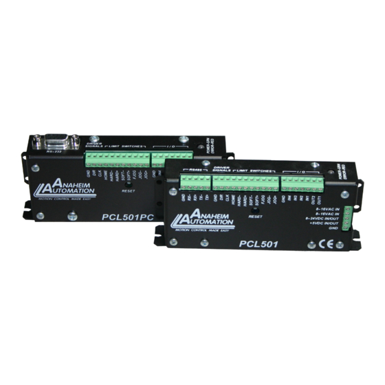
Page 1: Pcl501 / Pcl501Pc
PCL501 / PCL501PC Programmable Step Motor Controller User’s Guide A N A H E I M A U T O M A T I O N 4985 E Landon Drive, Anaheim, CA 92807 (714) 992-6990 fax: (714) 992-0471 e-mail: info@anaheimautomation.com website: www.anaheimautomation.com... -
Page 2: Table Of Contents
Table of Contents PCL501 / PCL501PC ............................1 Table of Contents ............................2 Section 1: Introduction ..........................3 Description ..............................3 Technical Support ............................3 Ordering Information .............................4 Axis Selection ...............................4 Baud Selection .............................5 Baud Rates ..............................5 Methods of Communication ..........................5 RS232 to RS485 Protocol ..........................5 RS485 Protocol ............................6... -
Page 3: Section 1: Introduction
The PCL501(PC) controller is an open-loop system, meaning that no information is sent back to the PCL501(PC) from the motor to verify the number of steps that were taken. A step motor is essentially a digital device - you give the step motor driver 10 step pulses, and the motor moves 10 steps. -
Page 4: Ordering Information
Axis Selection Each PCL501 will be addressed using 5 jumpers (JP4 - JP8) allowing the PC to address up to 32 PCL501s from one port. The jumpers are considered ON (1) when they are in position “1-2” and OFF (0) when they are in position “2-3”. -
Page 5: Baud Selection
4 or less inputs and 2 or less outputs can utilize a PCL501(PC) controller. RS232 to RS485 Protocol The PCL501 can be connected to your PC serial port via an RS485 or RS422 converter box. The RS232 converter will convert the RS232 communication format to the RS485 or RS422 format. Only one converter box is needed per serial port. -
Page 6: Rs485 Protocol
TX+ to RX+, and TX- to RX- on your converter box. Then run a wire from ground, a wire from TX+/RX+ and a wire from TX-/RX-, to the first PCL501 in the network. Finally do the same on the terminal block of the PCL501 as the converter box. -
Page 7: Terminating Resistor
To eliminate noise on the transmission lines a terminating resistor may need to be used. If needed the termination resistor need only be added to the last (furthest from the converter box) PCL501 in the network. A termination resistor with a value of 120 ohms is needed in certain conditions; when using a 4000 ft. or longer cable and a baud rate of 38400 or when using a 2000 ft. -
Page 8: Electrical Specifications
Logic “0”: 0 to 0.8VDC Note: For inductive loads, customers must connect a Logic “1”: 3.5 to 5.0VDC clamping diode to protect from fly back voltage spikes. Terminal Descriptions TB2: TB1: (PCL501 only) TB3: Pin # Description Comments Pin #... -
Page 9: Dimensions
Dimensions PCL501 PCL501PC #L010120 L010121 November 2001 July 2018... -
Page 10: Wiring Diagrams
Wiring Diagrams PCL501 PCL501PC L010121 #L010120 November 2001 July 2018... -
Page 11: Section 2: Functions
This command will move the motor the number of steps given. (Range: 0 to 8388607) Move to Position: The move to position command specifies the next absolute position to go to. The PCL501(PC) automatically sets the direction and number of steps needed to go to that position. (Range: -8388608 to +8388607) Home to Soft, Home Limit (2 Switch Operation): This type requires two grounding type limit switches called home and soft. - Page 12 Unless the finish move command is used, the PCL501(PC) will keep on executing commands, even though the PCL501(PC) is not ready to use it. This data will be ignored by the PCL501(PC), so the program will not work as expected.
- Page 13 Verify: The verify command causes the PCL501(PC) to send data back to the PC or PLC. The data is sent as an ASCII decimal string followed by a carriage return and a line feed. The permissible verify com- mands are shown below.
-
Page 14: Section 3: Smc50Win Software
Section 3: SMC50WIN Software The SMC50WIN software is a handy utility that supports Anaheim Automation’s line of PCL501(PC) and PCL511(PC) step motor controllers. Connecting your PC to the PCL501(PC), via a serial cable, the SMC- 50WIN software can easily perform the following tasks: •... -
Page 15: The Unit Is Connected" / "The Unit Is Not Connected
“The Unit is Connected” / “The Unit is NOT Connected” On the right of the Toolbar, the user will find the communication status of the PCL501(PC). If communications is not established, please refer to the troubleshooting section. File Menu New Program Start a new program. -
Page 16: Toolbar
Print the current program. Calculator Desktop calculator. Connect Establish communication with the controller. Tab Sheets Motion Controls and executes motion on the controller. Write and modify PCL501(PC) stored pro- Program grams. Motion Tab Sheet L010121 July 2018 #L010120 November 2001... -
Page 17: Motion Tab Sheet Tutorial
This tutorial will demonstrate the motion tab sheet: 1. Start the SMC50WIN software and power up the PCL501(PC). 2. Click the connect icon and establish communications with the PCL501(PC). 3. With the motion tab sheet displayed. 4. Enter 400 for the “Move number of steps below” button. -
Page 18: Program Tab Sheet
Program Tab Sheet Send Program to Send current program to the controller Controller View Program in View program in controller memory. Controller Enable Autostart Program will start when controller is powered up. Disable Autostart Program will only execute when run is clicked. Execute the program in the controller memory. -
Page 19: Smc50 Memory Available
With the program tab sheet selected the user can obtain the amount of available memory, located in the lower right corner of the SMC50WIN window. The PCL501(PC) has a maximum available memory of 2047 bytes - each instruction can use from 1 to 5 bytes. -
Page 20: Motion Command Tab Sheet
Motion Command Tab Sheet The motion command tab sheet controls the motion information of the motor such as Acceleration/ Deceleration, Maximum Speed, Base Speed, Move number of Steps, and etc. • It works similar to the Motion Tab Sheet explained above in the Getting Started section. •... - Page 21 Accel/Decel Set program acceleration and deceleration parameter. (step/sec Base Speed Set program base (start) speed rate. (step/sec) Max. Speed Set program maximum (running) speed rate. (step/sec) Set Position Set motor position. Move _______ Relative move command will allow motor to move the defined number of steps entered. Steps Move to Position Absolute move command will move motor to the position specified.
-
Page 22: Program Parameters
Program Parameters Goto The Goto command allows program to jump to specified address. The loop command allows a sequence of commands to be looped a specific Loop number of times to an address, which is lower in value. No nested loops are allowed. -
Page 23: Calculator
Calculator PPS- Convert from pulses per second to revolution per second. >RPS RPS- Convert from revolution per second to pulses per second. >PPS Enter the number of steps per revolution of the step motor. The Steps Per default is for a 200 step/rev motor in half step which is equal to 400. -
Page 24: Section 4: Direct Talk Mode
Section 4: Direct Talk Mode Direct mode is used to directly control motion for real time movements through serial communication. The PCL501(PC) has 20 commands which are easy to remember for direct movement of a step motor. COM Port Settings Baud Rate: Select one from the Baud Rate Selection chart in section 1. - Page 25 This command requests the PCL501(PC) to return the version number. ! - Error Codes Register Format : Description: This command requests the PCL501(PC) to get the current error code and print it to the screen. A - Acceleration/Deceleration Format: A [value]...
- Page 26 G - Go Number of Steps Format: Description: This command is used to send a set number of clocks out of the PCL501(PC). An N or P command must be entered before the G command. P - Absolute Position Format:...
- Page 27 H - Home Format: H [binary] Description: This command sends clocks out of the PCL501(PC) until the home limit or the soft limit is active. There are two types of homing available. Home Types: H0: In type 0 homing, the PCL501(PC) will send clocks until a soft limit is reached, then ramp down to base speed.
- Page 28 This command will ramp the clocks down to base speed. The move type then de- termines what will happen. In a relative or absolute type motion the PCL501(PC) will continue to the set position and stop. In a slew type motion the PCL501(PC) will ramp down and stop.
-
Page 29: Section 5: Troubleshooting
4) Was the software installed successfully? 5) Go to Setup | Communication Settings and verify COM port and baud rate settings. 6) Physically Verify that the Axis Address matches with the PCL501(PC) unit selected address. 7) Go to Setup | Axis and verify address setting. -
Page 30: Error Codes
1) Verify your program for improper syntax that may cause an error code. 2) Physically press the reset button on the PCL501(PC) to clear an error. 3) Another way to clear an error is by using either the SMC50WIN software or the direct mode command instructions set. -
Page 31: Section 6: Tutorial
Section 6: Tutorial Sample Program 1: Sample porgram 1 illustrates a typical application where a system moves to a specific position required. The sample program shows how to use the motion and goto instruction commands. 4000 8000 Start Initiate Values Move 4000 Steps Repeat Last Move Move to Position 0... -
Page 32: Sample Program 2
Sample Program 2: Sample program 2 illustrates a typical application where a system is first sent home to a datum or 0 po- sition. This sample program shows how a motor will move to 3 different positions utilizing some of the motion commands and loop routine. - Page 33 Start Initialize Parameters Home to Position 0 Move to 1st Position (Labeler) Move to 2nd Position (Dryer) Delay 1 Sec Move to 3rd Position (Capper) Loop 3 Times Quit July 2018 L010121 #L010120 November 2001...
-
Page 34: Appendix 1: Ascii Table For Direct Mode
Appendix 1: ASCII Table for Direct Mode ASCII Symbol Hex Value ASCII Symbol Hex Value Carriage Return 4C 30 4C 53 L010121 #L010120 November 2001 July 2018... -
Page 35: Copyright
Anaheim Automation will repair or replace at its option, any of its products which have been found to be defective and are within the warranty period, provided that the item is shipped freight prepaid, with RMA (return material authorization), to Anaheim Automation’s plant in Anaheim, California.
Need help?
Do you have a question about the PCL501 and is the answer not in the manual?
Questions and answers