Table of Contents
Advertisement
Quick Links
Advertisement
Table of Contents

Related Manuals for Anaheim Automation MDC100-050101USB


Summary of Contents for Anaheim Automation MDC100-050101USB
- Page 1 #L011213 July 2018...
-
Page 2: Table Of Contents
Table of Contents Section 1: Introduction ......................2 Description ..........................2 Methods of Communication ...................... 2 Baud Rate ........................... 3 Status LEDs ..........................3 Electrical Specifications ......................3 Control Inputs/Outputs ....................... 4 Ordering Information ......................... 4 Dimensions/Switch Locations ....................5 Wiring Diagrams ........................ -
Page 3: Section 1: Introduction
This driver will turn any USB port into a virtual comport, thus enabling simple commands to be sent to the MDC100-050101USB . To use the BMC100 software, the virtual comport driver must be installed. The MDC100-050101USB uses only 2 watts at 24 VDC with no motor running. -
Page 4: Baud Rate
This is often taken to mean the same as “bits per second,” a term that expresses only the number of “data” bits per second. Very often, the parity bit is included as an information or data bit. The MDC100-050101USB accepts a baud rate of 38400 only. Status LEDs When powered and operated properly, the PWR/ERR LED will be green. -
Page 5: Control Inputs/Outputs
BUSY Output: Open - Drain Type. Vce (max) = 40VDC, Ic (max) = 50mA This output will conduct current when active, and be open when not active. Current needs to be limited into this pin. For the MDC100-050101USB Series, this output is a complete output. Ordering Information The table below lists a variety of products available from Anaheim Automation, Inc. -
Page 6: Dimensions/Switch Locations
Dimensions/Inputs Locations Note: All units are in inches. Wiring Diagrams #L011213 July 2018... -
Page 7: Terminal Descriptions
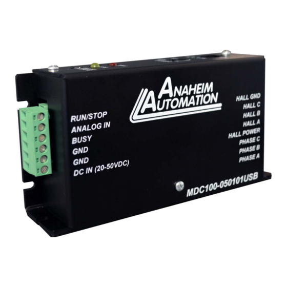
Terminal Descriptions Terminal Block 1. Position Description - Outputs to Motor Phase A Phase B Phase C HALL Power (5VDC) HALL A HALL B HALL C HALL GND Terminal Block 2. Position Description - Inputs Run/Stop Analog Input Voltage Busy DC Power Supply (20-50VDC) #L011213 July 2018... -
Page 8: Section 2: Functions
Section 2: Functions Run At Given Set Point: This command causes the motor to start spinning at the set point speed. The set point value is in RPM. When the Set Point speed is too high for the motor or the controller to reach or if the load is too much for the motor to handle, the motor will run at the maximum speed possible. -
Page 9: Pi Tuning
Read Error: This command reads the error. These errors are explained in the error codes section on page number 22. PI Tuning The MDC100-050101USB implements an optimized PI controller to control the speed of a brushless motor. The following chart will help you find the optimum settings for your system. Parameter... -
Page 10: Section 3: Bmc100 Windows Software
050101USB controller. The BMC100 uses a Serial Port and our proprietary Anaheim Automation protocol. This protocol is described in detail in the "Direct Talk Mode" Section. After connecting your PC to the MDC100-050101USB via a USB Cable, the BMC100 software can easily perform the following tasks: •... - Page 11 6. If the software did not automatically establish a connection with the controller, the user can manually connect to it after making sure that the controller is powered on and connected to the PC via USB. In order to do this, click on the Setup menu and then Connect.
-
Page 12: Bmc100 Settings And Functions
Motion Control Mode Sets Analog or Digital Mode Direction Set Clockwise or Counter Clockwise Direction Looking at Motor Shaft Freewheel Let the Motor Coast to a Stop when a Stop Command is Received Brake Immediately Stop the Motor when a Stop Command is Received Start Motor Run The Motor at the Set Point Speed Stop... -
Page 13: Section 4: Direct Talk Mode
Section 4: Direct Talk Mode Direct mode is used to directly control motion for real time movements through serial communication. The MDC100-050101USB controller has 34 commands, which are easy to remember for direct control of a Brushless DC motor. COM Port Settings... -
Page 14: Command Summary
Command Summary Note: * dash (_) after @ symbol represents the address of the unit. The range for the address is 0-99. All the commands are explained in detail at the end of the list. Other dashes(__) represent a parameter. **The dash in the specific command (@#__) represents any of the 34 commands above. - Page 15 RPM and analog max. RPM. The input will read a voltage between 0 and +5VDC, and based on the “upper and lower” limits of the function, a max speed can be obtained based on a calculated frequency between the two points. See examples below for calculations of the analog inputs. Analog calculations.
- Page 16 S - Start Motor Format: @0S(Carriage Return) Description: Starts the motor in Analog as well as in Digital mode. Example: When this command is sent, the motor starts running at the set point speed based on other configurations. If the motor is started with @0S in analog mode, it can only be stopped with @0, or @0.
- Page 17 M - Digital Set Point Speed Format: @0M(RPM Value)(Carriage Return) Description: Changes the set point speed of the digital mode to the speed represented by the dashes. It has no effect in Analog Mode. Example: @0M2600 will set the Digital Mode speed to 2600 revolutions per minute. If the motor is running in digital mode at any speed, the motor will run at 2600 rpm after this command is issued.
- Page 18 P - Set the Number of Poles Format: @0P(Number of Poles of Motor)(Carriage Return) Description: Checks and stores the number of poles as represented by the Number of Poles of motor. Example: This information is crucial for correct RPM calculations. The default number of poles is 4.
- Page 19 KP - Set Integrator Constant Format: @0KP(Integrator Value)(Carriage Return) Description: Checks and stores the Integrator constant as represented by the dashes. Example: @0KP20 will make the Integrator constant 20. The range for KP is 0-150. @0KP151 or @0KP1000 will return errors as described in the Error Codes Section. The default value is optimized for a 4 pole Brushless motor with small loads on them.
- Page 20 VN - Return the Lower Boundary of the Analog Mode Speed. Format: @0VN(Carriage Return) Description: Returns the lower boundary of the analog mode speed. Example: If the lower analog mode boundary is set to 1000 RPM, @0VN will return 'N1000' VX - Return the Upper Boundary of the Analog Mode Speed.
- Page 21 VMO - Returns the Mode. Format: @0VMO(Carriage Return) Description: Returns the Mode of the controller. Example: Factory default is A for analog mode. If the mode is set to Analog, @0VMO will return 'MOA.' If the mode is set to Digital, @0VMO will return 'MOD' VST - Return Configuration of Stop Bit.
- Page 22 VIV - Return the Initial Value Constant Format: @0VIV(Carriage Return) Description: Returns the current Initial constant for the power applied to the motor. The factory default is 0. The range for this is 0-1400. The higher the inertia of the load, the higher this value should be.
- Page 23 # - Match any Address Format: @#[Command](Carriage Return) Description: @# matches any address and executes the command that follows "#." Therefore, any command followed by @# is executed no matter what the profile is. Example: @#S will start the motor. @#P6 will set the number of poles to 6. #L011213 July 2018...
-
Page 24: Troubleshooting
Problem: Cannot establish communications with the MDC100-050101USB. Possible Solutions: 1) Make sure the MDC100-050101USB controller has power. Is the Green LED on? 2) Check the USB connections. 3) Check for loose cable connections on the MDC100-050101USB 4) Was the software installed successfully? 5) Go to Setup | Com Port Settings and verify COM port and baudrate settings. - Page 25 1. Invalid Command. @0G or @0k @0# @03 2. Invalid # of characters for the specified command. Too many characters in the command. @0S01, @0M234234, @0P123 @~100. 4. While motor is running, following instructions can't be performed. They are all checked for. These will be triggered only if the motor is running.
-
Page 26: Appendix 1: Ascii Table For Direct Mode
Appendix 1: ASCII Table for Direct Mode ASCII Symbol Hex Value ASCII Symbol Hex Value ASCII Symbol Hex Value " Carriage Return #L011213 July 2018... -
Page 27: Copyright
Anaheim Automation, Inc. will repair or replace at its option, any of its products which have been found to be defective and are within the warranty period, provided that the item is shipped freight prepaid, with RMA (return material authorization), to Anaheim Automation’s plant in Anaheim, California.
Need help?
Do you have a question about the MDC100-050101USB and is the answer not in the manual?
Questions and answers