Table of Contents
Advertisement
Quick Links
Advertisement
Table of Contents

Related Manuals for Anaheim Automation MDC151-024031 Series


Summary of Contents for Anaheim Automation MDC151-024031 Series
- Page 1 MDC151-024031 Series 24V, 3A Brushless DC Controller User’s Guide A N A H E I M A U T O M A T I O N 4985 E. Landon Drive Anaheim, CA 92807 (714) 992-6990 fax: (714) 992-0471 e-mail: info@anaheimautomation.com website: www.anaheimautomation.com...
-
Page 2: General Description
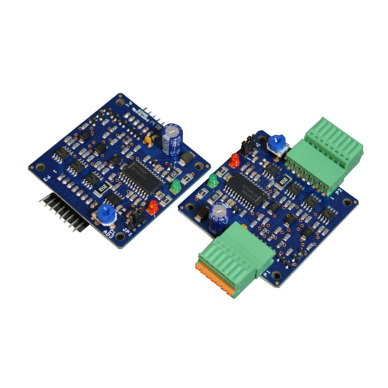
MDC151-024031 Driver Features • Fixed Current Limit Setting 3.0 Amps • 0V to 5V External Voltage Speed Control • 2-Quadrant Operation • Hall Sensor Feedback • Constant Velocity Mode • Short Circuit Protection • Requires 10 - 24VDC • Speed Out • Run/Stop, Freewheel and Direction • TTL-CMOS Compatible Inputs • Compact Size... -
Page 3: Specifications
Specifications Control Inputs:(P1, Pins 3-5) TTL-CMOS Compatible Logic “0” = 0-0.8VDC Logic “1” = OPEN All three inputs (run/stop, direction, and freewheel) are pulled up to 40k ohm resistors. Run/Stop: (P1, Pin 3) Logic “1” (open) - Motor will not run and if running will come to a hard stop Logic “0”... - Page 4 Under closed loop operation, the speed is regulated despite changes to the load. If using an Anaheim Automation DC Brushless motor, the tables shown on the next page are the Close Loop potentiometer and jumper settings for each motor. The regulated speed of the motor is then controlled by adjusting external speed input.
-
Page 5: Motor Connection
Commutation Sequence Step Step Phase A Phase A Phase B Phase B Phase C Phase C Hall A Hall A Hall B Hall B Hall C Hall C 120° Hall Spacing Sequence Forward 120° Hall Spacing Sequence Reverse Step Step Phase A Phase A Phase B... - Page 6 8-pin connector. These connectors are not supplied with the driver, but can be purchased from Anaheim Automation or AMP/Tyco Electronics. The two images below show how a hand tool can be used to quickly make the cable to connect to the driver.
-
Page 7: Terminal Descriptions
Speed Adjust Setting The speed may be varied at Vcontrol from 0V-5V maximum. If a voltage other than 0V to 5V is needed to control the speed of the motor, contact Anaheim Automation for custom tuning of the Vcontrol input. L011077... -
Page 8: Torque Curves
Speed Output The PG OUT terminal (P1 - pin 7) is used to determine the speed of the motor shaft. An open drain output is shown at a rate of 4 pulses for 1 revolution of an 8-pole motor, 3 pulses for 1 revolution of a 6-pole motor, and 2 pulses for 1 revolution of a 4-pole motor. - Page 9 Typical Wiring Diagram Dimensions MDC151-024031TB MDC151-024031 *All units in inches L011077 July 2013 July 2018...
- Page 10 Anaheim Automation will repair or replace at its’ option, any product which has been found to be defective and is within the warranty period, provided that the item is shipped freight prepaid, with previous authorization (RMA#) to Anaheim Automation’s plant in Anaheim, California.
Need help?
Do you have a question about the MDC151-024031 Series and is the answer not in the manual?
Questions and answers