Table of Contents
Advertisement
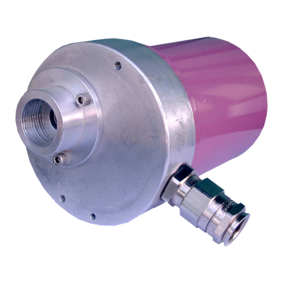
DYNAMIC SELF CHECK ULTRAVIOLET FLAME DETECTOR
model C7061A
model C7061F
APPLICATION
The C7061A is a dynamic self-checking flame detector for
sensing the ultraviolet radiation generated by the combustion
of gas, oil, or other fuels.
This flame detector is available in two versions:
model C7061A for use in Standard applications, and model
C7061F for use in installations requiring explosion-proof
packaging. The flame detector is designed for use with either,
R7061 Dynamic Self-Check Ultraviolet amplifier and
• R4348 Flame Switch or,
or with,
R7861A Dynamic Self-Check Ultraviolet amplifier and,
• 7800 SERIES Burner Programmers
These configurations provide a closed-loop, self-checking
circuit which insures the integrity of both amplifier and flame
detector. Improper response simulated flame loss results in
a safety shutdown and/or alarm.
Description .................................................................... 2
Features ......................................................................... 2
Orderdering information ................................................ 2
Specification .................................................................. 3
Standards and approvals .............................................. 4
Replacement parts and accessories ............................. 4
Dimensional drawing ..................................................... 5
Planning the installation ................................................ 6
Installation ..................................................................... 8
Wiring .......................................................................... 10
Adjustement and checkout ......................................... 12
Troubleshooting .......................................................... 13
Service ......................................................................... 14
1
C7061 A/F
PRODUCT HANDBOOK
CONTENTS
EN1C-0015SZ20 R0602
Advertisement
Table of Contents

Related Manuals for Honeywell C7061 A


Summary of Contents for Honeywell C7061 A
-
Page 1: Table Of Contents
C7061 A/F DYNAMIC SELF CHECK ULTRAVIOLET FLAME DETECTOR PRODUCT HANDBOOK APPLICATION The C7061A is a dynamic self-checking flame detector for sensing the ultraviolet radiation generated by the combustion of gas, oil, or other fuels. This flame detector is available in two versions:... -
Page 2: General Description
GENERAL DESCRIPTION The C7061A1020 and C7061F1003 detector models are The terminal block on both models is of wire clamp type with identical except for housings. removable screws and is situated in the compartment of the Model C7061F detector is for use in installations requiring C7061. -
Page 3: Technical Data Specification
TECHNICAL DATA SPECIFICATION Color: Violet. Specification Mounting flange (with heat block) and faceplate are separate Models to provide heat insulation and seal-Off. C7061A: Self checking UV flame detector in standard C7061F: housing. Meets requirements (explosion-proof): EEx d IIC T6 C7061F: Self checking UV flame detector in explosion proof Construction: cast-aluminum Cover. -
Page 4: Standards And Approvals
STANDARDS AND APPROVALS Models C7061A and F Model C7061F C7061A and F Ultraviolet Flame Detector conform with In addition to above information, C7061F conforms with: following EC-Directives: • Explosive Atmospheres Directive (94/9/EC)“according to • Gas Appliance Directive (90/396/EEC).“according to European Standards:“EN50014“EN50018“EN50019 European Standard:“EN298 approved with R7861 and Other approvals (C7061A only) R7061 flame amplifiers. -
Page 5: Dimensional Drawing
DIMENSIONAL DRAWING Fig. 1. Dimensional drawing C7061A in inches (mm) Fig. 2. Dimensional drawing C7061F in mm EN1C-0015SZ20 R0602... -
Page 6: Installation And Operation
INSTALLATION AND OPERATION PLANNING THE INSTALLATION Proper flame detector application is the back of a safe and Determine the location reliable flame safeguard installation. Refer to the burner Before beginning the actual installation, estimate the best manufacturer’s instructions as well to those included here. location for mounting the detector based upon these factors: Follow all instructions carefully. - Page 7 IMPORTANT Multiburner requirements When installing the detector, make sure it does In multiple burner systems, not every detector can be not respond to ignition spark. positioned so its line of sight does not intercept flames from other burners. This situation occurs in front-fired boiler Single burner requirements furnaces having more than one row of burners, or in multilevel The detector must have an unobstructed view of the flame it...
-
Page 8: Installation
INSTALLATION Mount Sight Pipe CAUTION Thread one end of the pipe to fit the mounting flange, union,or 1. lnstaller must be a trained, experienced flame required coupling. Cut the pipe to the desired length (as short safeguard control serviceman. as practical) and at an angle so it fits flush with the wall of 2. - Page 9 B Slightly rotate the detector so the slots in the back section of the mounting flange clear the screws in the front section; then separate the two sections. C Screw the front section of the mounting flange onto the sight pipe, reducer, or other fitting. Fig.
-
Page 10: Wiring
WIRING CAUTION CAUTION When using a C7061A/F with an R7061 or R7861 When using the C7061 in conjunction with an Dynamic Self-Check amplifier, be careful not to R4348 flame relay at 230VAC, parallel sensores short the white shutter lead wires together (by can not be used. - Page 11 Fig. 10_3. Wiring diagram for C7061A1020/C7061F1003 Fig.10_4. Wiring diagram for C7061A1020/C7061F1003 detector with 7800 SERIES Flame Safeguard detector with R4348B Flame Safeguard controls controls with shutter drive circuitry. with shutter drive circuitry. EN1C-0015SZ20 R0602...
-
Page 12: Adjustement And Checkout
ADJUSTMENTS AND CHECKOUT Adjust Detector Sighting Pilot Turndown Test With the flame detector installed and the burner running, If the detector is used to prove a pilot flame before the main adjust the sighting position of the detector for optimum flame fuel valve(s) can be opened, perform a pilot turndown test signal. -
Page 13: Various Troubleshooting
VARIOUS TROUBLESHOOTING CAUTION Preliminary lnspection A Check for the proper line voltage. Make sure the master 1. Be extremely careful while troubleshooting the switch is closed, connections are correct, and power detector; line voltage is present on some of supply is of the correct voltage and frequency. the terminals when power is on. -
Page 14: Service
SERVICE CAUTION Open the master switch to disconnect power before removing or installing the detector or its cover. More than one disconnect can be involved. Periodic Maintenance A Clean the viewing window (or focusing lens) when necessary. Remove the detector (see Troubleshooting section) and use a clean cloth over the eraser end of a pencil. - Page 15 Fig. 13. Replacing coil and shutter assembly. Replacing the Quartz Viewing Window (or Focusing Fig. 14. Replacing quartz viewing window or focusing lens Lens) C7061A Only IMPORTANT I Clean the viewing window (or focusing lens) on both sides A quartz window or lens must be used. Ordinary using a clean cloth placed over the eraser end of a pencil.
- Page 16 Automation & Control Solutions Automation & Control Solutions Automation & Control Solutions Automation & Control Solutions Automation & Control Solutions Control Product Satronic AG Honeywell-Platz 1 CH-8157 Dielsdorf Phone: +41 1 855 22 11 Fax: +41 1 855 22 22 EN1C-0015SZ20 R0602...
Need help?
Do you have a question about the C7061 A and is the answer not in the manual?
Questions and answers