
Related Manuals for Daheng Imaging VEN-134-90U3M-D


Summary of Contents for Daheng Imaging VEN-134-90U3M-D
- Page 1 China Daheng Group, Inc. Beijing Image Vision Technology Branch VEN-134-90U3M-D Board Level Cameras User Manual Version: V1.0.2 Date: 2019-07-09...
- Page 2 Notice All rights reserved. No parts of this manual may be used or reproduced, in any forms or by any means, without prior written permission of China Daheng Group, Inc. Beijing Image Vision Technology Branch. The right is also reserved to modify or change any parts of this manual in the future without prior notification. All other trademarks are the properties of their respective owners.
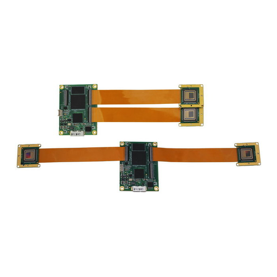
- Page 3 VEN-134-90U3M-D board level camera is small in size, supports binocular acquisition, and a variety of front-end data transmission cables (FPC) with optional length are available, which will be a good choice for users with board level binocular needs.
-
Page 4: Table Of Contents
Contents 1. Introduction ........................1 1.1. General Specifications .................... 1 1.2. Spectral Response ....................2 1.3. Mechanical Interface ....................2 1.3.1. Acquisition Board Mechanical Dimensions ................. 2 1.3.2. Imaging Board Mechanical Dimensions ................3 1.4. Software Interface ....................3 1.4.1. User Software Package ....................... 3 1.4.2. -
Page 5: Introduction
Operating Temp. 0° C~45° C Storage Temp. -20° C~70° C Operating Humidity 10%~80% Power Consumption <3.5W@5V Data Interface USB3.0 Regulations CE, RoHS, USB3.0 Vision, GenICam Table 1-1: VEN-134-90U3M-D general specifications © China Daheng Group, Inc. Beijing Image Vision Technology Branch... -
Page 6: Spectral Response
1. Introduction 1.2. Spectral Response Figure 1-1: VEN-134-90U3M-D spectral response 1.3. Mechanical Interface 1.3.1. Acquisition Board Mechanical Dimensions The following figure is the size of the acquisition board (units: mm). 4-φ2.2 is used for PCB board fixation. The maximum height of the top side (outside the screen) of the PCB board is 3, the maximum height of the bottom (in the screen) of the PCB board is 1.8. -
Page 7: Imaging Board Mechanical Dimensions
1.4. Software Interface 1.4.1. User Software Package The Software package of DAHENG IMAGING is used to control the VEN series camera, is to provide a stable, real-time image transmission, and provides an easy-to-integrate SDK and abundant development example source codes. The package is composed of the following modules: 1) Driver Package (Driver): This package provides the VEN series camera driver program, such as: the USB3.0 cameras’... -
Page 8: Application Programming Interface
1. Introduction the demonstration program, and also the user can develop their own control program based on the camera interface library. 4) Sample: The sample demonstrates the camera functions, the user can easily use these samples to control cameras, and also can refer to the samples to develop their own control program. 5) Programmer’s Manual: This manual is the users programming guide that instructs the users how to configure the programming environment and how to control camera and acquisition images through the camera interface library. -
Page 9: Guideline For Avoiding Emi/Esd
1. Introduction GenTL: a generic transport layer interface, between software drivers and libraries, that can be used for device enumeration, attribute control, and image acquisition. SFNC: common naming convention for camera features, which promotes interoperability between products from different manufactures. Figure 1- 1: GEN<i>CAM standard schematic diagram 1.5. -
Page 10: Environmental Requirements
1. Introduction 1.6. Environmental Requirements Housing temperature during operation:0° C ~ 45° C, humidity during operation: 10% ~ 80% (relative, non-condensing), storage temperature: -20° C ~ 70° C. PC requirement: Intel Core 2 Duo, 2.4GHz or above, and more than 2GB memory. USB3.0 host controller requirement: Intel controller integrated in mainboard is recommend. -
Page 11: Electrical Interface
2. Electrical Interface 2. Electrical Interface Here are two parts in the electrical interface: USB3.0 interface and I/O interface. By the USB3.0 interface, the camera can exchange data with the host and can power the camera, and can receive trigger signal and sync signal by the I/O interface. -
Page 12: Line2/Line3 (Bidirectional) Circuit
2. Electrical Interface 2.2.1. Line2/Line3 (bidirectional) Circuit Line2 can be configured as input or output through the software interface. Line3 is the same. The internal equivalent circuit of the camera is illustrated as follow. 3.3V INPUT2 Line2 INPUT3 Line3 OUTPUT2 OUTPUT3 Figure 2-2 GPIO2/3 (bidirectional) circuit 2.2.2. -
Page 13: Line2/3 Configured As Output
2. Electrical Interface 3.3V External Circuits INPUT2 Line2 Input Signal+ Input Signal- Figure 2-3 Equivalent circuit of camera when Line2 is configured as input Line2 INPUT2 0.8V TRIGIN_R_DELAY TRIGIN_F_DELAY Figure 2-4 Time delay parameter of the circuit when Line2 is configured as input To avoid the damage of IO pins, please connect GND pin before supplying power to Line2/3. - Page 14 2. Electrical Interface : <20μs (0°C~45° C) (parameter description as shown in Figure 2-5). Rising time delay = t : <20μs (0°C~45°C) (parameter description as shown in Figure 2-5). Falling time delay = t Delay parameters are affected greatly by external voltage and resistance, but little by temperature. Output delays in typical application conditions (temperature is 25°...
-
Page 15: Installation And Use
3. Installation and Use 3. Installation and Use 3.1. Hardware Installation Do not apply any force to the FPC cable at the end site (near FPC connector). There is an FPC connector on the acquisition board and imaging board, respectively, which is connected by FPC cable. - Page 16 3. Installation and Use Optimization of FPC cable folding and installation When the camera is installed into a specific position, the acquisition board and imaging board will have various relative positions of space. At this point, the FPC cable may be rotated or bent at middle site. In order to ensure that the FPC cable is in a free state, the FPC cable can be folded in advance according to the space position (avoiding the death fold, the turning radius above 1mm), and reducing the distortion and rotation of the stress to the FPC connector.
-
Page 17: Software Installation
3) If you are using USB3.0 Vision Cameras in Windows XP, and you have installed the Daheng Imaging Camera Software Suite without cameras connected to your PC, you must run Galaxy UpdateDriver firstly. -
Page 18: Faq
4. FAQ 4. FAQ General Question Answer In the non-activated Win7 64 bits After activating the Windows7 64 bits OS, uninstall OS, the installation of Galaxy SDK the software, then restart the OS, reinstall the has been successfully, but open the software and open the demo program again. -
Page 19: Revision History
5. Revision History 5. Revision History Version Changes Data V1.0.0 Initial release 2018-07-23 V1.0.1 Add description of GPIO output function 2019-05-09 V1.0.2 Add 10bit Pixel Bit Depth in 1.1 2019-07-09 © China Daheng Group, Inc. Beijing Image Vision Technology Branch...
Need help?
Do you have a question about the VEN-134-90U3M-D and is the answer not in the manual?
Questions and answers