Table of Contents
Advertisement
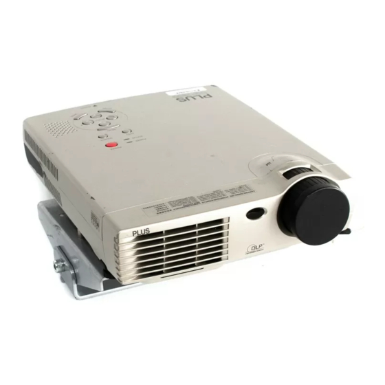
DATA PROJECTOR
U2-1200/U2-817
User's Manual
* DLP™ (Digital Light Processing) and DMD (Digital Micromirror Device) are registered trademarks of Texas Instru-
ments Incorporated (U.S.A.).
* DMD is an ultra-precise part developed by Texas Instruments (U.S.A.) which takes the place of liquid crystal (in the
projector).
* VGA and XGA are trademarks or registered trademarks of International Business Machines Corporation (U.S.A.).
* S-VGA is a registered trademark of Video Electronics Standards Association.
* Microsoft, Windows, and PowerPoint are registered trademarks of Microsoft Corporation (U.S.A. and other countries).
* Macintosh is a trademark of Apple Computer Inc. (U.S.A.).
* TMDS is a trademark of Silicon Image, Inc.
Note that even in the absence of explanatory notes, serious attention is paid to the trademarks of the various companies
and to the product trademarks.
IMPORTANT
Advertisement
Chapters
Table of Contents

Related Manuals for Plus U2-1200


Summary of Contents for Plus U2-1200
- Page 1 DATA PROJECTOR U2-1200/U2-817 User’s Manual * DLP™ (Digital Light Processing) and DMD (Digital Micromirror Device) are registered trademarks of Texas Instru- ments Incorporated (U.S.A.). * DMD is an ultra-precise part developed by Texas Instruments (U.S.A.) which takes the place of liquid crystal (in the projector).
-
Page 2: Important Safety Information
IMPORTANT SAFETY INFORMATION Precautions Please read this manual carefully before using your PLUS U2-1200/U2-817 Data Projector and keep the manual handy for future reference. TO PREVENT SHOCK, DO NOT OPEN THE CABINET. NO USER-SERVICEABLE PARTS INSIDE. REFER SERVICING TO QUALIFIED PLUS SERVICE PERSONNEL. -
Page 3: Important Safeguards
Do not insert any metal objects such as a wire or screwdriver into the unit. If something should fall into the unit, immediately disconnect the power cable from the unit and have the object removed by a qualified PLUS service person. • Do not place any liquids on top of the unit. -
Page 4: Major Features
Enable RGB output in addition to digital/analog RGB input... by using a DVI cable to connect the projector with a personal computer equipped with a DVI connector. This will allow fully digital pictures to be enjoyed. Also, by using the RGB output connector, the same image can be sent to the monitor of a personal computer. -
Page 5: Table Of Contents
Remote Control Range ... E-12 The Procedure Up to Projecting to the Screen ... E-13 Placement Guide ... E-14 U2-1200 Screen Size and Projection Distance ... E-14 U2-817 Screen Size and Projection Distance ... E-15 Connecting Personal Computers and Video Equipment ... E-16 Connections with Personal Computer ... -
Page 6: Table Of Contents
Table of Contents Color ... E-44 Gamma ... E-44 Color Temp..E-44 White ... E-44 Color Space ... E-45 White Balance ... E-45 View ... E-46 Aspect ... E-46 Filter ... E-46 Vertical Flip ... E-47 Keystone ... E-47 Keystone Save ... -
Page 7: Checking The Supplied Accessories
Remove the main unit and the accessories from the box and check that the following items are included. Remote control (includes one button battery) [1] This controls the projector. Please remove the transportation insulation sheet at time of purchase. (See Page E-12.) RGB signal cable (Mini D-sub 15-pin, 2 m / 6.6 feet) [1]... - Page 8 Checking the Supplied Accessories Carrying case (for projector and accessories) [1] This is a case designed for storing the projector and its accessories. Use this carrying case when storing or moving the pro- jector. User's Manual (CD-ROM edition) [1] User's Manual (Simplified Edition) [1]...
-
Page 9: Names Of The Main Unit Parts
Names of the Main Unit Parts Ventilation slots Front adjuster button [E-27] (There is also one on the right side.) Front adjusters [E-27] Remote control sensor [E-12] Exhaust vents Rear adjuster [E-27] Ventilation slots Lamp cover [E-63] Zoom ring [E-26] Focus ring [E-27] Lens Lens cap... - Page 10 Names of the Main Unit Parts POWER indicator [E-23,59] STATUS indicator [E-23,59] AUTO button [E-28] Buttons used in menu and toolbar operations ACCESS indicator [E-12] Ventilation slots RGB connector [E-17,20] DVI connector [E-16,17] Built-in Security Slot This security slot supports the MicroSaver Security System manufactured by Kensington Microware Inc.
-
Page 11: Names Of The Remote Control Parts
Names of the Remote Control Parts Infrared transmitter [E-12] POWER button [E-23,25] FREEZE button [E-30] (Freezes moving pictures) MUTE button [E-30] (Temporarily cancels the video and audio) QUICK button [E-34] (Displays a simplified menu) ASPECT button [E-29] (Selects the vertical and hori- zontal ratio of the screen) TIMER button [E-31] (Presentation timer time set-... -
Page 12: Preparing The Remote Control
• The indicator will not flash when bright light strikes the projector's remote control sensor or the remote control's transmitter, or when there is an obstacle located in between that blocks the signal. -
Page 13: The Procedure Up To Projecting To The Screen
When making connections with the video equipment's YCbCr connector or YPbPr connector, see "Connections with Component Signals" on Page E-20. When playing the audio through the built-in speaker of the projector, see "Connections with the AUDIO Jack" on Page E-21. -
Page 14: Placement Guide
* The projection distance (from the lens surface of the projector) within which focusing can be maintained is 1.20m / 3.94 feet to 13.81m/45.3 feet (for the U2-1200) and 1.20 m/3.94 feet to 17.70m/58.1 feet (for the U2-817). Please set up the projector within this range. -
Page 15: U2-817 Screen Size And Projection Distance
* There is a tolerance of ±5% due to design values. * This table uses the lens apex and lens center as references and requires that the projector be in a horizontal condition (with front and rear adjusters fully withdrawn). -
Page 16: Connecting Personal Computers And Video Equipment
• The projector has been set to "Auto" at the factory; however, if it does not project, please change the input setting to "Digital" using the menu sequence of [Setup] → [Input Format] → [DVI]. -
Page 17: Personal Computers With A Mini D-Sub 15-Pin Connector
Please orient the connector to mate properly when before inserting it, then turn the screw knobs to secure the connector to that of the projector. The projector has been set to "Auto" at the factory; however, if it does not project, please change the input setting to "RGB" using the menu sequence of [Setup] → [Input Format] → [RGB]. -
Page 18: To Output The External Output Signal Of A Notebook Computer
Should a sign not be output from the notebook computer, please try the operation described below. For an IBM PC/AT compatible computer, press the [Fn] key plus any one of the [F1] to [F12] keys. (See the table below.) Manufacturer... -
Page 19: Connections With Composite Signals
• Make the connection to the VIDEO connector of the projector using the supplied video cable. • The input setting of the VIDEO connector has been set to "Auto" at the factory; however, if the projector does not project, please change the input setting to "Your Country's Television Broadcast System"... -
Page 20: Connections With Component Signals
• Make connections to the RGB connector of the projector using a component cable, which is available separately. • The projector has been set to "Auto" at the factory; however, if it does not project, please change the input setting to "Compo- nent"... -
Page 21: Connections With The Audio Jack
Connections with the AUDIO Jack * Make the connection to the projector's AUDIO jack using the supplied audio cable. When the audio jack of the equipment that is to be connected is of the RCA phono type, make connection via the supplied audio conversion cable. -
Page 22: Connections With The Rgb Out Connector
• The screen of the personal computer that is connected to the RGB connector will be output. • While controlling the personal computer in front of you, the same screen can be projected with the projector. This allows personal computer control even from a position at which the projector image cannot be viewed. -
Page 23: Power Cable Connections And Switching The Power On/Off
Switch on the power of the connected equipment Note: • When the power plug will be unplugged from the power outlet, please place the projector near the power outlet so that it may be reached easily. • Press the POWER button or the POWER ON button after the POWER indicator is lit in amber. - Page 24 The first time the power is switched on after purchase, [Menu Lan- guage Select] will be displayed. Follow the procedure described be- low and select the display language of the projector. If the image is blurred, turn the focus ring counterclockwise or clock- wise to focus it.
-
Page 25: Finishing
POWER The [Power Off] display appears. When the level gauge reaches maximum, the projection screen will go off (in about 5 seconds) and the projector will enter the power-off op- eration. Note * The operation can be cancelled by pressing a button other than the POWER button. -
Page 26: Adjustment Of The Projection Screen
(3) If the image is slanted, adjust by turning the right or left front adjuster. See "Making Adjustments with the Adjusters" on Page E-27. (4) A projection image such as that illustrated in the diagram is the result of the projector not being perpendicular to the screen. Set the projector so that it is pointing straight toward the screen. -
Page 27: Making Adjustments With The Adjusters
Make adjustments so that there is no rattling. Note: When the projector has a suspended or rear installation is used, the orientation of the projection will need to be changed. Please see "Vertical Flip" on Page E-47. Focus ring... -
Page 28: General Operation
Note * When you do not operate source selection, the projector will assume the input selec- tion condition that was previously used. * See "Auto Source" on Page E-48 for information about the Auto Source on and off conditions. -
Page 29: Selection Of Aspect Ratio
16:9 screen Note: When selection has been made for the "Real" setting of the personal computer signal (i.e., when the input signal and the projector display resolution are high) and the "Zoom" setting of the video signal, pressing the SELECT position. -
Page 30: Freezing A Moving Picture
General Operation Freezing a Moving Picture This function is used to stop and view a moving picture. Note that the input image continues to advance even though the picture there is a still picture condition. A press of the FREEZE button changes the screen to a still picture. A further press returns the screen to a moving picture. -
Page 31: Using The Presentation Timer
Also, the timer will not be displayed unless a signal is being input. * While the presentation timer is being displayed, screen movement will not be possible in the zoom mode and the quick menu display will not operate with the projector buttons. buttons. -
Page 32: Keystone
Note: * Adjustment of the volume will not produce any sound unless an image is being projected. * Please make connections to the AUDIO connectors of the projector with the supplied audio cable. Press the “+” button. E-32... -
Page 33: Enlargement Of The Image And Video Movement
The image can also be moved in the following circumstances. • When "Aspect" is set to "Real" by the signal of the personal computer, and the input resolution is higher than the display resolution of the projector. • When "Aspect" is set to "Zoom" by the video signal. -
Page 34: Using The Quick Menu
General Operation Using the Quick Menu This function permits frequently used adjustments to be performed quickly. Note that the Quick Menu will not be displayed unless the signal of the connected equipment is input. Please select the input that you wish to adjust. Main unit operation (1) Press the SELECT button to display the quick ad-... -
Page 35: Menu Operation Method
• Adjustments and settings are made by projecting an image and adjusting to an optimum condition. • The remote control should be pointed toward the remote control sensor of the projector and operated. • To return the various items that have been changed via the menu to their standard values (i.e., default values at time of shipping from the factory), see "Factory Default"... -
Page 36: Menu Screen Names And Functions
Menu Operation Method Menu Screen Names and Functions Menu Name This is the title of the menu. There is a change to the title screen when the menu is se- lected. The selected menu name appears in red. Image Item Name This is the name of the ad- justment or setting. -
Page 37: Performing Menu Operations
Preparation Switch on the power of the connected equipment, start the play operation or another operation, and input the signal to the projector. Select the input that you wish to adjust. The menu display of the description diagram depicts an example in which the "Keystone" item name is selected. - Page 38 Menu Operation Method Displaying the Cursor Press the SELECT button to display the cursor ENTER Selection of the Item Name Press the SELECT ENTER Items for which the Icon Is Displayed A press of the ENTER button displays the sub menu and the cursor moves to the sub menu. Press the SELECT button and align the cursor with the desired item name.
-
Page 39: Selecting Another Menu Name With Remote Control Operation
Menu Operation Method Closing the Menu Press the MENU button and close the menu display ENTER Selecting Another Menu Name with Remote Control Operation When a sub menu is displayed, press the CANCEL but- ton and close the sub menu. Press the CANCEL button again and cancel the cursor display. -
Page 40: List Of Item Names Offering Input Selection And Adjustments/Settings
Menu Operation Method List of Item Names Offering Input Selection and Adjustments/Settings The item names that can be adjusted/set will differ depending on the input signal. [Example of Menu Display Items at the Time of Input Signal Analog RGB Selection] Image Brightness Contrast... - Page 41 Menu Operation Method Image Color Auto Source Auto Power Off Memu Position Lamp Mode Input Format Presentation Timer Logo Capture Option Menu name Item Name Setup Auto Source Auto Power Off Memu Position Lamp Mode Input Format Presentation Timer Logo Capture Option Info.
-
Page 42: Picture
Picture • Perform this operation while projecting the picture for which the adjustment/setting will be made. • Select the menu name "Picture". See "Menu Operation Method" on Page E-35 for information about performing menu operations. The item name display will differ depending on the input signal. -
Page 43: Reset
Picture Fine Picture Adjust this when the picture shows a lack of color fidelity or flickering. Select the "Fine Picture" item name and adjust with the SELECT so that the lack of color fidelity or the flickering disappears. H Position Adjust this when the picture is shifted to the left or right. -
Page 44: Color
Color • Do the following operation while displaying the image you want to adjust or set. • Select the menu name "Color". See "Menu Operation Method" on Page E-35 for information about performing menu operations. The item name display will differ depending on the input signal. -
Page 45: Color Space
Note * When the component signal undergoes conversion processing to red, green, and blue which express the image of the projector, the correct color cannot be reproduced unless a system compliant with the color difference conversion sys- tem of the input signal is used. Color Space serves to make this selection. -
Page 46: View
Filter This function sets the sharpness when the input signal is adjusted to the resolution of the projector and enlarged or reduced. Select the item name "Filter" and select the setting contents with the SELECT buttons. -
Page 47: Vertical Flip
Vertical Flip In selecting the method of projecting to the screen, these functions are set when the projector is in a suspended or a rear screen installation. Select the item name “Vertical Flip” or “Horizontal Flip” and select the setting contents with the SELECT buttons. -
Page 48: Setup
Note: Some video decks and other equipment output a blue background or other video when playback ends. When this happens, a signal is being input to the projector and Auto Power Off is not activated. Menu Position This function sets the display position of the menu. -
Page 49: Lamp Mode
Setup Lamp Mode Use this if the picture is projected on a small screen and the picture is too bright or when projecting images in dark rooms. Select the item name “Lamp Mode” and select the setting contents with the SELECT buttons. -
Page 50: Presentation Timer
Setup Presentation Timer The presentation is given while checking the timer displayed on the screen. The gauge display allows the remaining time to be known at a glance. Select the item name “Presentation Timer” and select the setting contents with the SELECT buttons. -
Page 51: Logo Position
Setup Logo Position This is the setting of the position for the display of the logo. Changes cannot be made after the capture. See "Startup Logo Creation" on Page E-57 for information about using logo capture. Select item name “Logo Capture”, press the ENTER button, and the sub menu will open. -
Page 52: Start Logo Capture
Setup Start Logo Capture This executes image capture. See "Startup Logo Creation" on Page E-57 for information about using logo capture. Select item name “Logo Capture”, press the ENTER button, and the sub menu will open. Select “Start Logo Capture” and press the ENTER button. There is a change to the capture range selection display. -
Page 53: Language
Setup Language This function sets the language that is displayed on screen in the messages and menu displays. Select item name “Options” and press the ENTER button to open the Options sub menu. Select item name “Language” and press the ENTER button to open the Language sub menu. -
Page 54: Startup Screen
Blank ... Does not display the logo. Note: * When "Logo" is selected at the startup screen, the "PLUS" logo will be displayed if the logo you created and captured is not set. * When logo capture is performed after "Blank" has been set, the setting of the starting screen will automatically display "Logo". -
Page 55: Info
There is a change to the status display. Press the CANCEL button to return to the menu. Display Contents: Projector model, firmware version, and the internet home page ad- dress of PLUS Vision Corp. Factory Default This function returns the adjustments and settings of all the in- put sources to the standard factory default values. -
Page 56: Resolution / Frequency
RGB or DVI has already been made. Lamp Timer This displays the lamp timer. This projector has an Eco mode function. The lamp life will differ between Normal mode and Eco mode. Lamp Life Use only in Normal mode: approx.3000 hours... -
Page 57: Startup Logo Creation
After turning on the power, a logo appears in about 15 seconds. The displayed logo disappears in about 30 seconds. A logo can be displayed by creating it on a personal computer, then projecting it with this projector and capturing it. - Page 58 Please make such photographs into a small size. * Capture ranges that exceed the output resolution of the projector cannot be se- lected. * The area outside the red lines of the red frame becomes the selection range for the capture range selection.
-
Page 59: When An Indicator Is Lit Or Flashing
2. Check the following matters and take the required measures. When the projector is being used in a location that has a high ambient temperature, set it up again in a cool location. Check the outflow and intake holes and clean them if they are obstructed. -
Page 60: Troubleshooting
• Does the projection distance exceed the focusing range? • Is there condensation on the lens, etc.? If the projector is moved from a cool storage area to a warm place and the power is turned on, condensation may form on the lens or internal optical parts. -
Page 61: Cleaning
Cleaning the Inside of the Projector Cleaning of the inside of the projector is required about once a year. Failure to clean over a long period while dust has collected inside the projector could cause a fire or breakdown. Do not clean the inside of the projector by yourself. Please be sure to contact your dealer. -
Page 62: Replacing The Lamp Cartridge
Replacing the Lamp Cartridge • The lamp that is used as a light source in the projector has a limited service life. The rated service life of the lamp is about 3000 hours (when used in normal mode only). This could be shortened depending on conditions of use and other factors. - Page 63 Replacing the Lamp Cartridge Preparations: Turning the projector upside-down on top of a soft cloth, etc., so that it does not get scratched makes it easier to replace the lamp cartridge. Turn the projector right-side up after replacing the lamp cartridge.
- Page 64 5 seconds will clear the lamp timer. Checking that the STATUS indicator is out will show that the lamp timer has been cleared. Contact a store that sells the U2-1200/U2-817 for a replacement lamp. Indicate you need a U2-210 replacement lamp for the U2-1200/U2-817 (order code 28-300).
-
Page 65: Specifications
Manual zoom ( 1.2), manual focus, F = 2.4 to 2.6, f = 26.5 to 31.8 mm Image size U2-1200: Minimum 27 inches (projection distance: 1.2 meters, tele mode) U2-817: Minimum 21 inches (projection distance: 1.2 meters, tele mode) Light Output... -
Page 66: Table Of Supported Frequency
Table of Supported Frequency The projector automatically identifies the signal input from the computer and selects the optimum resolution as shown on the table below. Manual adjustments may be required for some input signals. See “Picture Adj. / Fine Picture / H Position / V Position” on page E- 42, 43. -
Page 67: Cabinet Dimensions
Cabinet Dimensions ACCESS SELECT MENU SOURCE AUTO STATUS POWER POWER 230 (9.0) Unit: mm (inch) E-67...
Need help?
Do you have a question about the U2-1200 and is the answer not in the manual?
Questions and answers