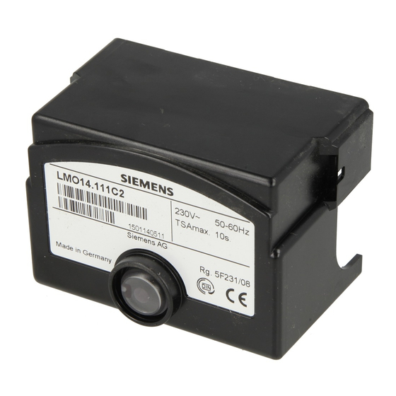
Siemens LMO14 Series Manual
Oil burner controls
Hide thumbs
Also See for LMO14 Series:
- Manual (14 pages) ,
- Manual (10 pages) ,
- Installation instructions manual (40 pages)
Advertisement
Quick Links
ISO 9001
Use, features
Use
General features
CC1N7130en
15.10.2002
Oil Burner Controls
Microcontroller-based oil burner controls for the startup, supervision and control
of forced draft oil burners in intermittent operation. Standard versions with an oil
throughput up to 30 kg / h, special versions above 30 kg / h.
The LMO14..., LMO24..., LMO44... and this Data Sheet are intended for use by
OEMs which integrate the burner controls in their products.
The LMO... are designed for the startup and supervision of single- or 2-stage forced
draft oil burners in intermittent operation. Yellow-burning flames are supervised with
photoresistive detectors QRB..., blue-burning flames with blue-flame detectors QRC...
In terms of housing dimensions, electrical connections and flame detectors, the LMO...
are identical with the LOA... oil burner controls.
Oil burners with fans to EN 267
-
Burner controls for use with atomization oil burners of monoblock design to EN 230
-
LMO44... for use with stationary direct-fired air heaters
-
Undervoltage detection
-
Electrical remote reset
-
Bridging contact for oil preheater
-
Monitoring of time for oil preheater
-
Accurate and reproducible control sequence through digital signal handling
-
Controlled intermittent operation after 24 hours of continuous operation
-
Limitation of the number of repetitions
-
Multicolor indication of fault and operational status messages
-
Siemens Building Technologies
HVAC Products
7
130
LMO14...
LMO24...
LMO44...
Advertisement

Subscribe to Our Youtube Channel
Summary of Contents for Siemens LMO14 Series
- Page 1 Monitoring of time for oil preheater Accurate and reproducible control sequence through digital signal handling Controlled intermittent operation after 24 hours of continuous operation Limitation of the number of repetitions Multicolor indication of fault and operational status messages Siemens Building Technologies CC1N7130en HVAC Products 15.10.2002...
-
Page 2: Installation Notes
Never run the detector cable together with other cables – Line capacitance reduces the magnitude of the flame signal – Use a separate cable · Observe the maximum permissible lengths of the detector cables (refer to «Techni- cal data») 2/12 Siemens Building Technologies CC1N7130en HVAC Products 15.10.2002... -
Page 3: Commissioning Notes
Use the service adapters KF8885 / KF8833 / KF8840 for only short periods of time Disposal notes The unit contains electrical and electronic components and may not be disposed of together with household waste. Local and currently valid legislation must be observed. 3/12 Siemens Building Technologies CC1N7130en HVAC Products 15.10.2002... -
Page 4: Mechanical Design
LOA44.252A27 TSAmax. Maximum ignition safety time Legend Waiting time Prepurge time t1’ Purge time Preignition time Postignition time Interval from flame signal to release of «BV2» Bridging contact for oil preheater ¹) 4/12 Siemens Building Technologies CC1N7130en HVAC Products 15.10.2002... - Page 5 With on / off switch for simulating the flame signal With holes for checking the control voltages at the tabs of the burner control With one pair of jacks for measuring the flame detector’s resistance 5/12 Siemens Building Technologies CC1N7130en HVAC Products 15.10.2002...
- Page 6 > 45 µA QRC... < 45 µA > 45 µA The values given in the table above only apply under the following conditions: - Mains voltage AC 230 V - Ambient temperature 23 °C 6/12 Siemens Building Technologies CC1N7130en HVAC Products 15.10.2002...
- Page 7 Blue Black Brown QRB... QRC1... As an alternative to detector current measurement, the diagnostic tool OCI400 / ACS400 can be used. In that case, connection of a DC microammeter is not required. 7/12 Siemens Building Technologies CC1N7130en HVAC Products 15.10.2002...
- Page 8 Limitation of repetitions If the flame is lost for the fourth time during operation, the burner will initiate lockout. The repetition count is restarted each time controlled switching on by «R-W-SB» takes place. 8/12 Siemens Building Technologies CC1N7130en HVAC Products 15.10.2002...
- Page 9 Fault, alarm Error code output (refer to «Error code Flashing red table») s s s s s s s s Interface diagnostics Red flicker light Legend ..Steady on Yellow Green 9/12 Siemens Building Technologies CC1N7130en HVAC Products 15.10.2002...
- Page 10 The diagnostics of the cause of fault is quit and the burner switched on again by reset- ting the burner control. Press the lockout reset button for about 1 second (< 3 seconds). 10/12 Siemens Building Technologies CC1N7130en HVAC Products...
- Page 11 Operating position «OH» Start of startup sequence with burners using no Controlled shutdown by «R» Time of flame establishment Control signals µC1 Microcontroller 1 Required input signals µC2 Microcontroller 2 Perm. input signals 11/12 Siemens Building Technologies CC1N7130en HVAC Products 15.10.2002...
- Page 12 Dimensions Dimensions in mm LMO... 41,64 88,5 LMO14.111B2 ã 2002 Siemens Building Technologies Subject to change! 12/12 Siemens Building Technologies CC1N7130en HVAC Products 15.10.2002...


Need help?
Do you have a question about the LMO14 Series and is the answer not in the manual?
Questions and answers