Vanguard Instruments EZCT User Manual
Digital current-transformer testers
Hide thumbs
Also See for EZCT:
- Operating procedures manual (47 pages) ,
- Calibration instruction (4 pages)

Subscribe to Our Youtube Channel
Related Manuals for Vanguard Instruments EZCT


Summary of Contents for Vanguard Instruments EZCT
- Page 1 EZCT and EZCT-10 DIGITAL CURRENT-TRANSFORMER TESTERS USER’S MANUAL Vanguard Instruments Company, Inc. 1520 S. Hellman Ave. Ontario, California 91761, USA TEL: (909) 923-9390 February 2010 FAX: (909) 923-9391 Revision 4...
- Page 2 SAFETY WARNINGS AND CAUTIONS The EZCT/EZCT-10 can produce a voltage up to 1,200 Vac that can cause severe injury and/or equipment damage. Due to this reason, the EZCT/EZCT-10 shall be used only by trained operators.
-
Page 3: Table Of Contents
Performing a Diagnostics Test ..................46 Verifying the EZCT’s V Sense Circuit Using an External Meter ........48 Verifying the EZCT’s I Sense Circuit Using an External Meter ........49 Quickly Verifying the EZCT’s Turns Ratio Circuit ............50 Troubleshooting Guide ....................51... - Page 4 LIST OF TABLES Table 1. EZCT Technical Specifications ................... 4 Table 2. EZCT-10 Technical Specifications ..................5 Table 3. Functional Descriptions of EZCT/EZCT-10 Controls and Indicators ........7 Table 4. Descriptions of Tabulated Test Results Elements ............22 LIST OF FIGURES Figure 1.
-
Page 5: Conventions Used In This Document
Menu options are referenced as (MENU OPTION). • Both the EZCT and the EZCT-10 are simply referred to as “EZCT” in this manual. The exact model number is used only in cases where differences between the units are discussed. •... -
Page 6: Introduction
User Interface The EZCT features a back-lit LCD screen (4 lines by 20 characters) that is viewable in both bright sunlight and low-light levels. A rugged, alpha-numeric, membrane keypad is used to enter test information and to control the unit’s functions. The test voltage range (50V at 2A, 200V at 2A, 1,200V at 1.5A) is selected with a switch on the control panel. -
Page 7: Furnished Accessories
EZCT/EZCT-10 USER’S MANUAL Computer Interface The EZCT can be used as a stand-alone unit or can be computer-controlled via the built-in RS- 232C or USB interfaces. Windows® XP/Vista-based Current Transformer Analysis software is provided with each EZCT. This software can be used to retrieve test records from the EZCT and can also be used to run CT tests from the PC. -
Page 8: Technical Specifications
EZCT/EZCT-10 USER’S MANUAL REV 4 Technical Specifications 1.3.1. EZCT Technical Specifications Table 1. EZCT Technical Specifications TYPE Portable current-transformer test set PHYSICAL SPECIFICATIONS 16.8”W x 12.6”H x 12”D (42.7 cm x 32 cm x 26.9 cm); Weight: 55 lbs (25 Kg) INPUT POWER 100 –... -
Page 9: Ezct-10 Technical Specifications
REV 4 EZCT/EZCT-10 USER’S MANUAL 1.3.2. EZCT-10 Technical Specifications Table 2. EZCT-10 Technical Specifications TYPE Portable current-transformer test set PHYSICAL SPECIFICATIONS 16.8”W x 12.6”H x 12”D (42.7 cm x 32 cm x 26.9 cm); Weight: 55 lbs (25 Kg) INPUT POWER 100 –... -
Page 10: Controls And Indicators
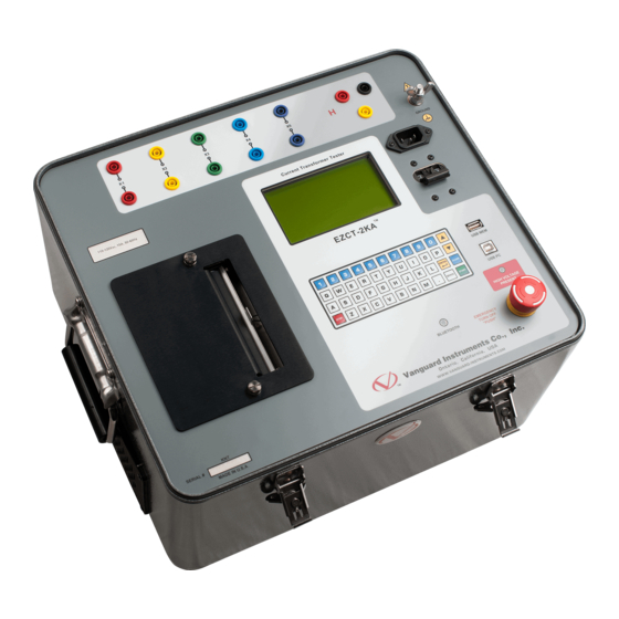
REV 4 Controls and Indicators The EZCT and EZCT-10 feature the same controls and indicators shown in Figure 1. A leader line with an index number points to each control and indicator, which is cross-referenced to a functional description in Table 3. The table describes the function of each item on the control panel. -
Page 11: Table 3. Functional Descriptions Of Ezct/Ezct-10 Controls And Indicators
REV 4 EZCT/EZCT-10 USER’S MANUAL Table 3. Functional Descriptions of EZCT/EZCT-10 Controls and Indicators Item Panel Markings Functional Description Number Current transformer excitation voltage connector. Current transformer primary input test cable connector. 50V, 200V, 1200V Test voltage selector switch. HIGH VOLTAGE LED warning indicator that is illuminated when high voltage is present. -
Page 12: Pre-Test Setup
EZCT/EZCT-10 USER’S MANUAL REV 4 PRE-TEST SETUP Operating Voltages The EZCT’s operating voltage is preset at the factory for 100-120 Vac, 50/60 Hz or 200-240 Vac, 50/60 Hz. LCD Screen Contrast Control [PAPER ∧ Contrast] To increase the LCD screen contrast, press and hold the key for two seconds. - Page 13 The thermal paper will show a red stripe to indicate that the roll is about to run out of paper. Computer Interface Ports The EZCT features one USB and one RS-232C PC interface port. A Windows-based “Current Transformer Analysis” software application is supplied with the EZCT. For further information, please see the software user’s manual.
-
Page 14: Operating Procedures
OPERATING PROCEDURES EZCT Cable Connections Always connect the EZCT to the substation ground before connecting any test cables. The EZCT is supplied with a 20-foot X test cable and a 35-foot H cable. Only the X cable connection is required to run the transformer excitation test. The H and X cable connection is required to run the transformer ratio test. -
Page 15: Figure 3. Connection To Ct's On Y Transformer
REV 4 EZCT/EZCT-10 USER’S MANUAL Figure 3. Connection to CT’s on Y Transformer Figure 4. Connection to CT's on a Delta Transformer... -
Page 16: Figure 5. Typical Ezct Connection To Multiple Ct's
EZCT/EZCT-10 USER’S MANUAL REV 4 Figure 5. Typical EZCT Connection to Multiple CT’s... -
Page 17: Performing Tests
REV 4 EZCT/EZCT-10 USER’S MANUAL Performing Tests 3.2.1. Entering Test Record Header Information You can enter the test record header information before performing tests. The record header includes identifying information such as the company, station, circuit, model number, etc. Once the header information has been entered, it will apply to all subsequent test records. - Page 18 EZCT/EZCT-10 USER’S MANUAL REV 4 ∨ Contrast] [ENTER] key to move to the previous character. Press the key when you are done typing the company name. e. The following screen will be displayed: STATION: ↑↓ TO POSITION “ENTER” TO ACCEPT...
- Page 19 REV 4 EZCT/EZCT-10 USER’S MANUAL i. The following screen will be displayed: SERIAL NUMBER: ↑↓ TO POSITION “ENTER” TO ACCEPT [ENTER] Type the serial number using the alpha-numeric keypad and then press the key. j. The following screen will be displayed: COMMENTS: ↑↓...
-
Page 20: Performing An Excitation And Ratio Test
0.8A. • IEC 60044-1 10/50 is equivalent to ANSI 10/50. a. When the EZCT is turned on, it will first go through a start-up cycle and load the firmware. Then the “START-UP” menu will be displayed as shown below: 1. - Page 21 NOTE [VOLTAGE CONTROL] Turn the knob clockwise until the test current displayed is about 2.0A (10.0A for the EZCT-10). As you turn the knob, the screen will be updated as shown: SET SATURATION POINT “ENTER” TO CONTINUE I = 2.1005 AMPS V = 360.0...
- Page 22 EZCT/EZCT-10 USER’S MANUAL REV 4 g. The following screen will be displayed: XFMR NAME PLATE RAT. 1. YES 2. NO 1. YES Press the key (YES) to enter the name plate ratio. The following screen will be displayed: ENTER PLATE RATIO: Input the first (“high side”) number using the numeric keypad.
- Page 23 PRINTING REPORT PLEASE WAIT... A typical EZCT tabulated report printout is shown in figure Figure 6, and the report elements are described in Error! Reference source not found.. A typical EZCT excitation graph is shown in Figure 7.
- Page 24 (YES) to save the test record. n. The following screen will be displayed: RECORD NUMBER 1 HAS BEEN SAVED! The EZCT will automatically assign a record number and will not over-write existing records in memory. NOTE [ENTER] Press the key.
-
Page 25: Figure 6. Typical Ezct Tabulated Report Printout
REV 4 EZCT/EZCT-10 USER’S MANUAL Figure 6. Typical EZCT Tabulated Report Printout... -
Page 26: Table 4. Descriptions Of Tabulated Test Results Elements
Excitation voltage used in CT turns ratio test. Excitation current in turns ratio test. • ANSI 10/50 is shown as ASA 10%V 50%I on the EZCT LCD menu. • ANSI 10/50 is printed as ASA 10/50 on the tabulated report printout. -
Page 27: Performing A Turns Ratio Only Test
EZCT/EZCT-10 USER’S MANUAL 3.2.3. Performing a Turns Ratio Only Test The EZCT performs the CT turns ratio test using the voltage method. Also, if the name plate ratio is entered, the EZCT will calculate the percentage error by comparing the CT measured ratio against the name plate ratio. - Page 28 EZCT/EZCT-10 USER’S MANUAL REV 4 ENTER PLATE RATIO: 80 : Input the second (“low side”) number using the numeric keypad and press the [ENTER] key: ENTER PLATE RATIO: 80 : 1.0 Continue to step d. 2. NO Press the key (NO) if you do not want to enter the name plate ratio.
- Page 29 REV 4 EZCT/EZCT-10 USER’S MANUAL e. The following screen will be displayed: PRINT TEST RESULTS? 1. YES 2. NO Press the key (YES) to print the test results on the built-in thermal printer. The following screen will be displayed while the report is being printed: PRINTING REPORT PLEASE WAIT...
-
Page 30: Figure 8. Typical Turns Ratio Only Test Report Printout
(YES) to save the test record. The following screen will be displayed: j. The following screen will be displayed: RECORD NUMBER 1 HAS BEEN SAVED! The EZCT will automatically assign a record number and will not over-write existing records in memory. NOTE [ENTER] Press the key. -
Page 31: Working With Test Records
Working With Test Records 3.3.1. Printing a Test Record Directory You can print a directory of the test records stored in the EZCT’s Flash EEPROM on the unit’s built-in thermal printer. To print a test record directory: a. Start from the “START-UP” menu: 1. -
Page 32: Figure 9. Sample Test Record Directory Printout
EZCT/EZCT-10 USER’S MANUAL REV 4 Figure 9. Sample Test Record Directory Printout... -
Page 33: Restoring And Printing A Test Record From Flash Eeprom
3.3.2. Restoring and Printing a Test Record From Flash EEPROM You can restore a test record from the EZCT’s Flash EEPROM to the working memory. You can then print the restored test record on the unit’s built-in thermal printer. To restore a test record: a. - Page 34 EZCT/EZCT-10 USER’S MANUAL REV 4 Type the record number using the alpha-numeric keypad and then press the [ENTER] key. Continue to step e. 2. SCROLL TO SELECT Press the key (SCROLL TO SELECT) to scroll through a directory of test records and select the desired test record from the directory.
-
Page 35: Figure 10. Typical Abbreviated Test Record Printout
REV 4 EZCT/EZCT-10 USER’S MANUAL and Interpolated Data Points. The test record will be printed and you will be returned to the “START-UP” menu. 2. NO Press the key (NO) if you do not want to print the test record at this time. -
Page 36: Printing A Restored Test Record
EZCT/EZCT-10 USER’S MANUAL REV 4 3.3.3. Printing a Restored Test Record If you restored a test record (see section 3.3.2) but did not print it at the time that it was restored, you can still print it at a later time. To print the test record in the working memory: a. -
Page 37: Erasing Test Records From The Flash Eeprom
REV 4 EZCT/EZCT-10 USER’S MANUAL 3.3.4. Erasing Test Records From the Flash EEPROM You can erase individual or all test records stored in the EZCT’s Flash EEPROM. To erase a test record: a. Start from the “START-UP” menu: 1. RUN TEST 08/27/09 2. - Page 38 EZCT/EZCT-10 USER’S MANUAL REV 4 The following screen will be displayed while the record is being erased: ERASING RECORD NUMBER 3 PLEASE WAIT... The following screen will be displayed when the record has been completely erased: RECORD NUMBER 3 ERASED!
-
Page 39: Changing Setup Parameters
REV 4 EZCT/EZCT-10 USER’S MANUAL CHANGING SETUP PARAMETERS Setting the Knee Point Marker Use the steps below to change the knee point marker for the excitation graph: a. Start from the “START-UP” menu: 1. RUN TEST 08/27/09 2. SETUP 10:10:25 3. -
Page 40: Figure 11. Graphic Report Showing Knee Point Marker
EZCT/EZCT-10 USER’S MANUAL REV 4 Knee Point Marker Knee Point Marker Type Figure 11. Graphic Report Showing Knee Point Marker... -
Page 41: Selecting The Buried Ct In Transformer Delta Option
REV 4 EZCT/EZCT-10 USER’S MANUAL Selecting the Buried CT in Transformer Delta Option 4.2.1. Enabling the Buried CT in Transformer Delta Option If you are measuring the turns ratio of a CT buried in the transformer Delta windings (see Figure 12 and Figure 13 for further information), you must first select the “Buried CT in Delta”... -
Page 42: Disabling The Buried Ct In Transformer Delta Option
EZCT/EZCT-10 USER’S MANUAL REV 4 f. The following screen will be displayed: RATIOS ADJ BY 2/3 ARE YOU SURE? 1. YES 2. NO Press the key (YES). g. The following screen will be displayed: -BURIED CT IN DELTA- RATIOS ADJUSTED BY TWO-THIRDS Press any key to return to the “START-UP”... - Page 43 REV 4 EZCT/EZCT-10 USER’S MANUAL d. The following screen will be displayed: 1.BURIED CT DLTA ON 2.BURIED CT DLTA OFF Press the key (BURIED CT DLTA OFF). e. The following screen will be displayed: BURIED CT DELTA IS OFF. RATIOS DISPLAYED AS MEASURED.
-
Page 44: Figure 12. Buried Ct In A Delta Transformer Illustration 1
EZCT/EZCT-10 USER’S MANUAL REV 4 Figure 12. Buried CT in a Delta Transformer Illustration 1 Figure 13. Buried CT in a Delta Transformer Illustration 2... - Page 45 • The CT turns ratio is now measured as Ratio = or Ratio = ). This measured turns ratio is higher than the actual turns ratio. • The EZCT will display the correct CT turns ratio by adjusting the measured turns ratio by...
-
Page 46: Setting The Clock
EZCT/EZCT-10 USER’S MANUAL REV 4 Setting the Clock To set the EZCT’s internal clock: a. Start from the “START-UP” menu: 1. RUN TEST 08/27/09 2. SETUP 10:10:25 3. DIAGNOSTIC Press the key (SETUP). b. The following screen will be displayed: 1. -
Page 47: Setting The Option To Print Impedance (Z) In The Tabulated Results
Setting the Option to Print Impedance (Z) in the Tabulated Results The EZCT can print the CT impedance (Z) values in the tabulated results (see Figure 14). The impedance values are the quotient of the excitation voltage divided by the current reading at each data point. - Page 48 EZCT/EZCT-10 USER’S MANUAL REV 4 e. The following screen will be displayed: PRINT IMPEDANCE (Z)? 1. YES 2. NO Press the key (YES) if you would like the impedance values to be printed on the tabulated report. The option will be set and you will be returned to the “START-UP”...
-
Page 49: Figure 14. Tabulated Report Printout With Impedance Values
REV 4 EZCT/EZCT-10 USER’S MANUAL Impedance Values Figure 14. Tabulated Report Printout with Impedance Values... -
Page 50: Diagnostics, Verification, And Troubleshooting
EZCT/EZCT-10 USER’S MANUAL REV 4 DIAGNOSTICS, VERIFICATION, AND TROUBLESHOOTING Performing a Diagnostics Test The Diagnostics test mode displays the excitation voltage (V ), the voltage sensed by the H leads ), and the X voltage excitation current (I ). These values can then be verified using an external volt meter and ampere meter. - Page 51 REV 4 EZCT/EZCT-10 USER’S MANUAL e. The following screen will be displayed: PLEASE TURN VOLTAGE DRIVE TO ZERO… [VOLTAGE CONTROL] Turn the knob counter-clockwise back to zero. You will then be returned to the “START-UP” menu.
-
Page 52: Verifying The Ezct's V X Sense Circuit Using An External Meter
Verifying the EZCT’s V Sense Circuit Using an External Meter The excitation voltage (V ) sensed by the EZCT can be verified using an external RMS volt meter. Follow the steps below to verify the EZCT’s V sense circuit: a. Connect the X cables to an RMS volt meter as shown in Figure 15. -
Page 53: Verifying The Ezct's I X Sense Circuit Using An External Meter
Turn the knob clockwise to raise the V voltage. d. Verify the I voltage displayed on the EZCT’s LCD screen against the value displayed on the external RMS ampere meter. [STOP] e. Press the key to end the test. -
Page 54: Quickly Verifying The Ezct's Turns Ratio Circuit
REV 4 Quickly Verifying the EZCT’s Turns Ratio Circuit You can quickly verify the EZCT’s turns ratio circuit by performing the following ratio test: a. Connect the X1 test lead to the H1 test lead as shown in Figure 17. -
Page 55: Troubleshooting Guide
The excitation current can be raised during a test. When running the • The EZCT X cable is driving an opened • Check the CT terminal connection. excitation test, the V circuit. voltage can be raised but the excitation current is always zero during a test. - Page 56 1520 S. Hellman Ave • Ontario, CA 91761 • USA Phone: 909-923-9390 • Fax: 909-923-9391 www.vanguard-instruments.com Copyright © 2009 by Vanguard Instruments Company, Inc. EZCT and EZCT-10 User’s Manual • Revision 4.4 • February 17, 2010 • TA...
Need help?
Do you have a question about the EZCT and is the answer not in the manual?
Questions and answers