
Subscribe to Our Youtube Channel
Related Manuals for Vanguard Instruments EZCT


Summary of Contents for Vanguard Instruments EZCT
- Page 1 OPERATING PROCEDURES for the EZCT EZCT-10 Digital Current Transformer Tester Vanguard Instruments Co., Inc. 1520 S. Hellman Ave. Ontario, California 91761 TEL: 909-923-9390 July 2005 FAX: 909-923-9391 REV. 2...
- Page 3 Precaution with High Test Voltage Because the EZCT can produce a voltage up to 1,200Vac, this high voltage can cause severe injury, death, and/or equipment damage. The device shall be used only by trained operators.
-
Page 5: Table Of Contents
6.5 Print Test Record Directory Procedure ................33 6.6 Erase Test Record Procedure ....................35 6.7 Computer Interface Procedure .................... 36 6.8 Set EZCT Real Time Clock Procedures ................37 6.9 Set Knee Point Marker......................38 6.10 Print (Z) Impedance In The Tabulated Results ..............39 6.11 Diagnostic ......................... - Page 6 Table 17 Print Impedance Procedures..................39 Table 18 EZCT Diagnostic Procedures ..................41 LIST OF FIGURES Figure 1 EZCT Control Panel (Controls and Indicators) ............7 Figure 2 EZCT-10 Control Panel (Controls and Indicators) ............9 Figure 3 Typical EZCT Cable Connection .................. 12 Figure 4 Connection to CTs on Wye Transformer...............
-
Page 7: Safety Summary
CT excitation voltage and current, turns ratio, and winding polarity on single or multi-ratio current transformers. The EZCT provides a variable AC test voltage up to 1,200Vac for the CT excitation test. Test voltage and excitation current readings are displayed on the LCD and recorded during a test. -
Page 8: Furnished Test Accessories
Both the EZCT and EZCT-10 have the same functional features. The only difference is that the EZCT-10 has more output current on the 50Vac and the 200Vac test voltages. The EZCT test voltage and current output ranges are: 50Vac @ 2A, 200Vac @ 2A, 1200Vac @ 1.2A The EZCT-10 test voltage and current output ranges are: 50Vac @ 10A, 200Vac @ 10A, 1200Vac @ 1.2A... -
Page 9: EzctAnd Ezct-10Specifications
Operating Procedures EZCT and EZCT-10 2.0 EZCTAND EZCT-10SPECIFICATIONS Table 1 EZCTSpecifications MODEL........... EZCT TYPE ............Special-purpose test equipment, Current Transformer tester POWER ..........85 to 132Vac or 200-240Vac (factory preset), 50/60 Hz SIZE (inches) .......... 16.8 wide by 12.6 high by 10.6 deep WEIGHT .......... -
Page 10: Table 2 Ezct-10Specifications
Operating Procedures EZCT and EZCT-10 Table 2 EZCT-10Specifications MODEL........... EZCT-10 TYPE ............Special-purpose test equipment, Current Transformer tester POWER ..........85 to 132Vac or 200-240Vac (factory preset), 50/60 Hz SIZE (inches) .......... 16.8 wide by 12.6 high by 10.6 deep WEIGHT .......... -
Page 11: Controls And Indicators
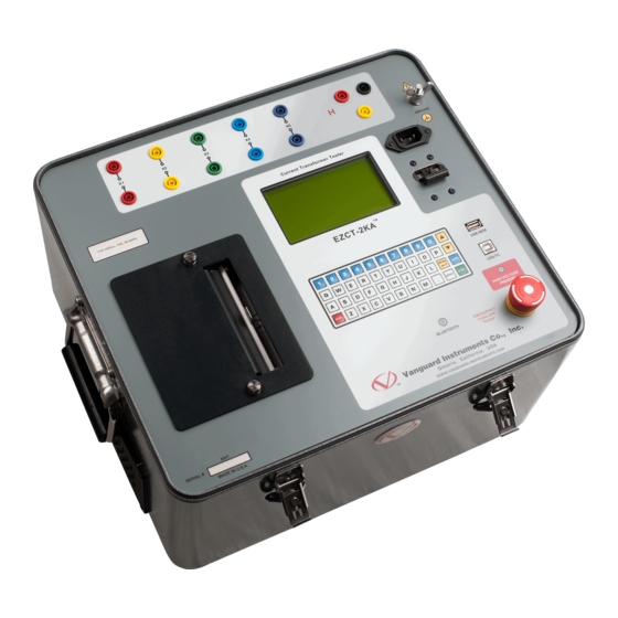
(See Figure 1 and refer to Table 3.0). The EZCT controls and indicators are shown in a panel illustration (see Figure 1). Pointing leader lines reference each item in the figure with an index number. Each index number is cross- referenced to a functional description in Table 3.0, which describes the purpose of each item on... -
Page 12: Table 3 Ezct Controls And Indicators
20A built-in circuit breaker. (no marking) AC receptacle. GROUND Ground Stud RS-232C Connector, 9-pin; Serial interface-port connector (female DB type) to allow the EZCT to be controlled by an IBM-compatible PC. SIGNAL Signal Gnd VOLTAGE Test voltage control knob CONTROL (no marking) Operating key-pad controls;... -
Page 13: Ezct-10 Controls & Indicators
(See Figure 2 and refer to Table 4.0). The EZCT-10 controls and indicators are shown in a panel illustration (see Figure 2). Pointing leader lines reference each item in the figure with an index number. Each index number is cross- referenced to a functional description in Table 4.0, which describes the purpose of each item on... -
Page 14: Table 4 Ezct Controls And Indicators
20A built-in circuit breaker. (no marking) AC receptacle. GROUND Ground Stud RS-232C Connector, 9-pin; Serial interface-port connector (female DB type) to allow the EZCT to be controlled by an IBM-compatible PC. SIGNAL Signal Gnd VOLTAGE Test voltage control knob CONTROL (no marking) Operating key-pad controls;... -
Page 15: Pretest Setup
4.2 EZCT LCD Contrast Control The EZCT uses a 4 lines by 16 characters back-lighted LCD. To Darken the LCD display, press a n d h o l d t h e “ P a p e r C o n t r a s t ” s w i t c h f o r t w o s e c o n d s a n d t h e L C D w i l l b e g i n t o d a r k e n . T o l i g h t e n t h e L C D d i s p l a y , p r e s s a n d h o l d t h e “... -
Page 16: Ezct Cable Connections
Always connect the EZCT to the substation ground before connecting any test cables. The EZCT is supplied with a 20-foot X test cable and a 35-foot H cable. Only the X cable connection is required to run the current transformer excitation test. The H and X cable connection is required to run the transformer ratio test. -
Page 17: Figure 4 Connection To Cts On Wye Transformer
Operating Procedures EZCT and EZCT-10 Figure 4 Connection to CTs on Wye Transformer Figure 5 Connection to CTs on a Delta Transformer... -
Page 18: Figure 6 Typical Ezct Connection To Multiple Cts
Operating Procedures EZCT and EZCT-10 Figure 6 Typical EZCT Connection to Multiple CTs... -
Page 19: Operating Procedures
Test or a Turns Ratio Test only. 6.1.1 Run Excitation and Ratio test When a user runs an excitation test, the EZCT applies an AC voltage to the CT secondary winding. The user raises this AC voltage until the CT windings reach the saturation point. The user then slowly lowers the test voltage back to zero volts. -
Page 20: Table 5 Run Excitation And Ratio Test (Continued)
Run the transformer ratio test by pressing key XFMR NAME PLATE RAT. #1 (YES). 1.YES 2.NO To have the EZCT calculate the percentage ENTER PLATE RATIO error, enter the transformer nameplate ratio by pressing key #1 (YES). 5-10 Enter the transformer nameplate ratio. -
Page 21: Table 5 Run Excitation And Ratio Test (Continued)
, a n “ A p p e n d D a t a ” message will be displayed. In this case, go to 5-16A. None. The EZCT allows the user to append 5-16A PREVIOUS DATA IN BUF. - Page 22 Press key #2 to save record. Continue on 5- 1.RUN TEST 11/27/06 2.SETUP 09:45:00 Press key #1 to abort save record, the EZCT 3.DIAGNOSTIC will return to MAIN MENU. NOTE A typical test contains a excitation and turns ratio test. A record may contain 10 tests.
-
Page 23: Figure 7 Typical Ezct Tabulated Report Printout
E Z C T ™ a n d E Z C T - 1 0 Operating Procedures Knee Point Voltage ANSCI 10/50 CT Turns ratio Test Results Phase angle and measurement Figure 7 Typical EZCT Tabulated Report Printout... -
Page 24: Figure 8 Typical EzctExcitation Graph
E Z C T ™ a n d E Z C T - 1 0 Operating Procedures Knee Point Marker Figure 8 Typical EZCTExcitation Graph... -
Page 25: Run Ratio Only Test
Operating Procedures 6.1.2 Run Ratio Only Test The EZCT performs the CT turns ratio test using the voltage method. The EZCT can also compare the CT measured ratio against the name plate ratio and generate the percentage error. The percentage error is calculated as follows: % E r r o r = [ ( Me a s u r e d r a t i o –... -
Page 26: Table 6 Run Ratio Only Test (Continued)
E Z C T ™ a n d E Z C T - 1 0 Operating Procedures Table 6 Run Ratio Only Test (continued) STEP ACTION DISPLAY To run the ratio test, turn the voltage knob S E T R A T I O V L T G N O W… to set the test voltage to the desired value. -
Page 27: Figure 9 Ratio Only Test Report Printout
Press key #1 (YES) to save the record. RECORD NUMBER 3 NOTE HAS BEEN SAVED! The EZCT will assign a record number for the test record saved in FLASH EEPROM. Press the STOP key to return to the Main 6-14 menu. -
Page 28: Ezct Test Record Id
E Z C T ™ a n d E Z C T - 1 0 Operating Procedures 6.2 EZCT Test Record ID 6.2.1 Enter Test Record ID Procedure This procedure allows the user to enter the equipment identification information to be used with the test record. -
Page 29: Table 7 Enter Test Record Id Procedure (Continued)
When finished, press 2.SETUP 16:27:00 ENTER to store the data and return to the 3.DIAGNOSTIC MAIN MENU display. This completes the ENTER ID procedure. NOTE The EZCT will retain the test record ID in memory until it is changed by the operator. -
Page 30: Ezct Test (Shot) Record Id Directory
6.2.2 EZCT Test (Shot) Record ID Directory The EZCT can store 10 test record IDs in its internal memory. The test record IDs are generated by using the Current Transformer Analysis Software PC program. Once the test ID is generated, it can be downloaded and stored in the EZCT via the RS-232C interface. -
Page 31: Figure 10 Test Record Id Directory Printout
E Z C T ™ a n d E Z C T - 1 0 Operating Procedures Figure 10 Test Record ID Directory Printout... -
Page 32: Load Test Record Id Procedure
EZCT keypad. Ten test record IDs can be stored in the EZCT memory. Test record IDs are generated by using the using the Current Transformer Analysis Software PC program and down-loading them to the EZCT. -
Page 33: Restore Record Procedure
E Z C T ™ a n d E Z C T - 1 0 Operating Procedures 6.3 Restore Record Procedure This procedure describes how to restore a test record residing in EZCT Flash EEPROM to working memory. The user can then print the test record with the thermal printer. NOTE The EZCT can store up to 128 test records in the FLASH EEPROM. -
Page 34: Print Record Procedure
If more than one test is included in a test record, the excitation curves will be combined and printed on one graph. The user can print test record residing in EZCT working memory using the steps below. Table 11 Print Record Procedures... - Page 35 E Z C T ™ a n d E Z C T - 1 0 Operating Procedures F i g u r e 1 1 T y p i c a l E Z C T “ A b b r e v i a t e d ” T a b u l a t e d R e s u l t s P r i n t O u t...
-
Page 36: Figure 12 Typical Graphic Results Print Out With Multiple Excitation Curves
E Z C T ™ a n d E Z C T - 1 0 Operating Procedures Figure 12 Typical Graphic Results Print Out With Multiple Excitation Curves... -
Page 37: Print Test Record Directory Procedure
E Z C T ™ a n d E Z C T - 1 0 Operating Procedures 6.5 Print Test Record Directory Procedure This procedure describes the steps to print the test record directory of test records stored in the EZCT Flash EEPROM. Table 12 Print Test Record Directory STEP ACTION EZCT... -
Page 38: Figure 13 Typical Test Record Directory Printout
E Z C T ™ a n d E Z C T - 1 0 Operating Procedures Figure 13 Typical Test Record Directory Printout... -
Page 39: Erase Test Record Procedure
T h i s p r o c e d u r e d e s c r i b e s t h e s t e p s t o d e l e t e o n e o r a l l o f t h e t e s t r e c o r d s s t o r e d i n t h e E Z C T ’ s Flash EEPROM. Table 13 Erase Test Record Procedure STEP ACTION EZCT DISPLAY On the MAIN MENU, press key #2 13-1 1.ENTER ID (SETUP) to select the SETUP MENU 2.PRINT RECORD... -
Page 40: Computer Interface Procedure
3.KNEE POINT MARKER 4.SET Z PRINT ON/OFF Press key #1 (COMPUTER CONTROL) to 14-3 place the EZCT u n d e r a n e x t e r n a l P C ’ s COMPUTER ITF MODE control. NOTE To end the PC control mode, press the STOP key. -
Page 41: Set Ezct Real Time Clock Procedures
E Z C T ™ a n d E Z C T - 1 0 Operating Procedures 6.8 Set EZCT Real Time Clock Procedures This procedure describes the steps to set the EZCT real time clock. Table 15 Set Clock Procedures STEP ACTION EZCT... -
Page 42: Set Knee Point Marker
The user can select which knee point marker to use with the following procedure. Table 16 Set Knee Point Marker Procedures STEP ACTION EZCT DISPLAY On the MAIN MENU, press key #2 1.ENTER ID (SETUP) to select the SETUP MENU 2.PRINT RECORD... -
Page 43: Print (Z) Impedance In The Tabulated Results
The user can turns on or off the impedance print out on the test report by using the following procedures. Table 17 Print Impedance Procedures STEP ACTION EZCT DISPLAY On the MAIN MENU, press key #2 17-1 1.ENTER ID (SETUP) to select the SETUP MENU 2.PRINT RECORD... -
Page 44: Figure 14 Tabulated Report With Impedance Print Out
E Z C T ™ a n d E Z C T - 1 0 Operating Procedures Figure 14 Tabulated Report with Impedance Print Out... -
Page 45: Diagnostic
(Ix) outputs and the H input voltage (Vh) simultaneously on the display. This feature allows the user to trouble shoot a connection problem to a CT or to verify the EZCT excitation voltage and current readings against external meters. - Page 46 E Z C T ™ a n d E Z C T - 1 0 Operating Procedures APPENDIX A EZCT and EZCT-10Troubleshooting Guide Item Symptom Possible Problem Solution Turns ratio reading is 1. No H cable connection. 1. Check for H cable connection.
- Page 47 1520 S. Hellman Ave, Ontario, CA 91761, USA Phone: 909-923-9390 Fax: 909-923-9391 Website: http//www.vanguard-instruments.com EZCT 07/13/06: OAK...
Need help?
Do you have a question about the EZCT and is the answer not in the manual?
Questions and answers