Table of Contents

Subscribe to Our Youtube Channel
Related Manuals for Vanguard Instruments RFD-200 2 Series


Summary of Contents for Vanguard Instruments RFD-200 2 Series
- Page 1 Operating Procedures RFD-200 S2™ USER’ S MANUAL For the Model RFD-200 Series 2 Portable Relay Test Set Vanguard Instruments Company 1520 S. Hellman Ave. Ontario, California 91761 TEL: (909) 923 9390 October 2006 FAX: (909) 923 9391 Rev. 1...
- Page 2 Operating Procedures RFD-200 S2™ SAFETY SUMMARY Always Follow Exact Operating Procedures Any deviation from the procedures described in this operators’ manual may create one or more safety hazards, damage the Model RFD-200 S2, or cause errors in the test results; Vanguard Instruments Co., Inc.
-
Page 3: Table Of Contents
Operating Procedures RFD-200 S2™ Table of Content 1.0 INTRODUCTION .......................1 1.1 General Description......................1 1.2 Functional Description ......................2 1.3 Furnished Test Accessories ....................2 2.0 RFD-200 S2 Specifications ....................3 3.0 CONTROLS AND INDICATORS..................4 3.1 RFD-200 S2 Auxiliary Power Supply................6 3.2 RFD-200 S2 Current Source and Voltage Sources.............6 3.3 RFD-200 S2 Control Switches...................7 3.4 Timer Start and Timer Stop Inputs ..................8 3.5 RFD-200 S2 Power Resistors ....................9... -
Page 4: Introduction
Operating Procedures RFD-200 S2™ 1.0 INTRODUCTION 1.1 General Description The Model RFD-200 Series 2 (or RFD-200 S2) is a second-generation, microprocessor-based, single-phase relay tester. The Model RFD-200 S2 was designed specifically to test electromechanical, electronic, and microprocessor–based current or voltage relays. An AC current source with 3 outputs (10A, 40A, and 100A) provides test current to the relays but can also be used as a stand alone current source. -
Page 5: Functional Description
Operating Procedures RFD-200 S2™ 1.2 Functional Description The RFD-200 S2 is designed specifically to test single-phase (over/under) voltage and current protection relays. Since the current source is capable of outputting up to 100A, the RFD-200 is ideal for testing electromechanical protection relays. The RFD-200 S2 can also be used as an AC current source and AC or DC voltage source. -
Page 6: Rfd-200 S2 Specifications
Operating Procedures RFD-200 S2™ 2.0 RFD-200 S2 Specifications Table 1.0 RFD-200 S2 Specifications MODEL..........RFD-200 S2 TYPE ............ Special-purpose test equipment, Single Phase Relay ............. tester INPUT POWER........90 - 130 V ac or 210-240 V ac (user specified), 50/60 Hz SIZE ... -
Page 7: Controls And Indicators
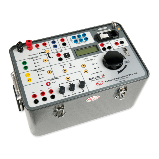
Operating Procedures RFD-200 S2™ 3.0 CONTROLS AND INDICATORS (See Figure 1.0 and refer to Table 2.0). The RFD-200-S2 controls and indicators are shown in the front panel illustration (see Figure 1.0 below). Pointing leader lines reference each item in the figure with an index number. - Page 8 Operating Procedures RFD-200 S2™ Table 2.0 RFD-200 S2 Controls and Indicators Fig. 1 Index PANEL MARKING FUNCTIONAL DESCRIPTION 1 & 2 TIMER START Timer Start Input Connectors. Current source common. Timer Stop Selection Switch. 100A 100A current source terminal. Timer Start selection Switch. 40A current source terminal METER SELECT Internal/External current display selection...
-
Page 9: Rfd-200 S2 Auxiliary Power Supply
Operating Procedures RFD-200 S2™ 3.1 RFD-200 S2 Auxiliary Power Supply The RFD-200 S2 provides 3 auxiliary power supplies (24Vdc, 124Vdc, 240Vac) to power electronic relays. Each power supply is fuse protected. These power supply outputs are controlled by the AUX PWS ON/OFF switch. A LED is lit to indicate when power supply output is turned on. -
Page 10: Rfd-200 S2 Control Switches
Operating Procedures RFD-200 S2™ 3.3 RFD-200 S2 Control Switches The RFD-200 S2 control switches and voltage and current source control knob are shown in figure 4. The Voltage and current sources are controlled by the up (? ) and down (? ) switches. -
Page 11: Timer Start And Timer Stop Inputs
Operating Procedures RFD-200 S2™ 3.4 Timer Start and Timer Stop Inputs The RFD-200 S2 built-in timer displays the test results in both millisecond and cycles. There are 3 selections for the Timer Start Input: Internal: Timer starts when voltage/current sources are turned on or off (user select Start-On mode or Start-Off mode). -
Page 12: Rfd-200 S2 Power Resistors
Operating Procedures RFD-200 S2™ 3.5 RFD-200 S2 Power Resistors Five power resistor connections are available on the RFD-200 S2 front panel. By connecting one or more resistors in series with the current source, the users can achieve a finer control of the current output from the current source. Figure 6 Power Resistor Array 3.6 RFD-200 S2 External Voltage Input One external voltage input is available on the RFD-200 S2. -
Page 13: Rfd-200 S2 Application
Operating Procedures RFD-200 S2™ 4.0 RFD-200 S2 Application 4.1 Setting Voltage or Current source Note In the following instruction steps, all references to panel controls, indicators and terminals will be exactly as marked on the panel and are noted in bold capital letters. Perform the following steps to select and set the voltage or current source. -
Page 14: Set Rfd-200 S2 For A Time Delay Test
Operating Procedures RFD-200 S2™ 4.2 Set RFD-200 S2 for a Time Delay Test Perform the following steps to measure an over-current relay time delay. 1. Connect the RFD-200 S2 current source output across the relay coil. 2. Select INTERNAL for timer start. The INTERNAL indicator will light. 3. -
Page 15: Figure 10 Typical Circuit Breaker Timing Connection
Operating Procedures RFD-200 S2™ 4.3 Use RFD-200 S2 Timer to Test a Circuit Breaker Response Time The following steps set the RFD-200 S2 timer to measure the opening time of a circuit breaker. The timer will start when the RFD-200 S2 detects the voltage being applied to the circuit breaker trip coil. -
Page 16: User Rfd-200 S2 Timer In The Single Input Mode
Operating Procedures RFD-200 S2™ 4.4 User RFD-200 S2 Timer in the Single Input Mode The RFD-200 S2 timer can be started and stopped with the START INPUT only. This feature is handy to measure the time duration of the START INPUT when it changes states then returns to the previous state. -
Page 17: Use Rfd-200 S2 To Plot A Current Transformer Excitation Curve
Operating Procedures RFD-200 S2™ 4.5 Use RFD-200 S2 to Plot a Current Transformer Excitation Curve The following steps to find the excitation curves of a CT. 1. Connect RFD-200 S2 AC voltage source to the CT secondary winding in series with the External Current Input (see Figure 11). -
Page 18: Use Rfd-200 S2 To Measure Ct Primary And Secondary Current
Operating Procedures RFD-200 S2™ 4.6 Use RFD-200 S2 to Measure CT primary and Secondary Current Perform the following steps to set the RFD-200 S2 to measure the primary and secondary current readings 1. Connect the RFD-200 S2 current source through the CT primary current path. 2. - Page 19 Operating Procedures RFD-200 S2™ 1520 S. Hellman Ave., Ontario, CA 91761, USA Phone 909-923-9390 Fax 909-923-9391 www.vanguard-instruments.com RFD-200 S2 Rev 1 10/ 2006...
Need help?
Do you have a question about the RFD-200 2 Series and is the answer not in the manual?
Questions and answers