
Subscribe to Our Youtube Channel
Related Manuals for Vanguard Instruments VBT-75 S2


Summary of Contents for Vanguard Instruments VBT-75 S2
- Page 1 VBT-75 S2 VACUUM BOTTLE TESTER USER’S MANUAL Vanguard Instruments Company, Inc. 1520 S. Hellman Ave. Ontario, California 91761, USA TEL: (909) 923-9390 July 7, 2017 FAX: (909) 923-9391 Revision 1...
- Page 2 Operating Voltage: The VBT-75 S2 is rated for use with an operating voltage of 120V or 240V, auto-ranging ±10% of selected voltage. Power Cord: The VBT-75 S2 is supplied with a 16 AWG, 16A power cord with a NEMA 5-15P plug. Replacement cable shall have the same or better rating and is available through the manufacturer.
-
Page 3: Table Of Contents
Updating Firmware ......................11 LIST OF TABLES Table 1. VBT-75 S2 Technical Specifications ................... 3 Table 2. Functional Descriptions of VBT-75 S2 Controls and Indicators ........5 LIST OF FIGURES Figure 1. VBT-75 S2 Controls and Indicators .................. 4 Figure 2. VBT-75 S2 Connection Diagram ..................6... -
Page 4: Conventions Used In This Document
REV 1 VBT-75 S2 U USER’S MAN CONVENT TIONS US SED IN TH HIS DOCU UMENT This docu ument uses the followin ng conventio ons: WITCH] • A key y or switch o on the VBT-7 75 S2 is indic cated as •... -
Page 5: Introduction
VOLTAGE” LED light. For additional operator safety, an “ARM” switch must be held down during testing. The VBT-75 S2 features a back-lit LCD screen (20 characters by 4 lines) that is viewable in both bright sunlight and low-light levels. A turn-and-press knob is used to control the unit. The VBT- 75 S2's firmware can be updated in the field via the unit's built-in USB Flash drive port. -
Page 6: Technical Specifications
REV 1 VBT-75 S2 U USER’S MAN Technical S Specificatio Table 1. VBT-75 S2 2 Technical S Specification TYPE P Portable 75 kV vacuum bottle tester Dimensions: 1 7”W x 10.5”H x x 6.5” D (42.7 cm x 26.9 cm x x 16.5 cm) -
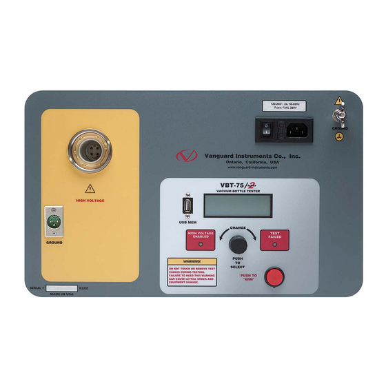
Page 7: Vbt-75 S2 Controls And Indicators
REV 1 VBT-75 S2 Controls and Indicators The VBT-75 S2’s controls and indicators are shown in Figure 1 below. A leader line with an index number points to each control and indicator, which is cross-referenced to a functional description in Table 2. The table describes the function of each item on the control panel. The purpose of the controls and indicators may seem obvious, but users should become familiar with them before using the VBT-75 S2. -
Page 8: Table 2. Functional Descriptions Of Vbt-75 S2 Controls And Indicators
REV 1 VBT-75 S2 USER’S MANUAL Table 2. Functional Descriptions of VBT-75 S2 Controls and Indicators Item Panel Markings Functional Description Number HIGH VOLTAGE High voltage cable connector USB MEM USB flash drive interface for firmware updates Back-lit LCD screen (4 lines x 20 characters). -
Page 9: Cable Connections
VBT-75 S2 USER’S M MANUAL REV 1 CABLE CO ONNECT TIONS The VBT- -75 S2 come s furnished with one 10 -foot (3.05m m) high volta age cable and d one 10-foo voltage r return cable. . Both cables s are termin ated with al lligator clam mps that are... -
Page 10: Operating Procedures
REV 1 VBT-75 S2 USER’S MANUAL OPERATING PROCEDURES Set the Date and Time Follow the steps below to set the date and time for the VBT-75 S2's internal clock: a. Start from the "START-UP" menu: [RUN TEST] 07/06/17 SETUP 11:03:05... -
Page 11: Changing The Lcd Screen Contrast
VBT-75 S2 USER’S MANUAL REV 1 Changing the LCD Screen Contrast Follow the steps below to adjust the VBT-75 S2's LCD screen contrast: a. Start from the "START-UP" menu: [RUN TEST] 07/06/17 SETUP 11:03:05 CABLE VTG: [CONTROL KNOB] Turn the... -
Page 12: Performing A Test
REV 1 VBT-75 S2 USER’S MANUAL Performing a Test Follow the steps below to perform a test: a. Start from the “START-UP” menu: [RUN TEST] 07/06/17 SETUP 11:03:05 CABLE VTG: [CONTROL KNOB] The RUN TEST option should be enclosed in brackets. Press the b. - Page 13 [PUSH TO "ARM"] Press the red switch. g. The VBT-75 S2 will initiate the test and start the timer based on the test duration selected. The screen will be updated with the test voltage and the leakage current as shown below: TEST IN PROGRESS 59.31 μA...
-
Page 14: Updating Firmware
"Software/Firmware Downloads" link: c. All Vanguard products will be listed along with any compatible firmware and software. Scroll down the page to find the VBT-75 S2 listing and then click on the firmware link to save the firmware file. - Page 15 VBT-75 S2 USER’S M MANUAL REV 1 e. C opy the file "vbt75s2.he ex" to the ro ot folder of a USB Flash drive. • Please u use an empt ty flash drive e. Please bac ckup any exi isting files an then de elete them fr rom the driv...
- Page 16 1520 S. Hellman Ave • Ontario, CA 91761 • USA Phone: 909-923-9390 • Fax: 909-923-9391 www.vanguard-instruments.com Copyright © 2017 by Vanguard Instruments Company, Inc. VBT-75 S2 User’s Manual • Revision 1.0 • July 27, 2017 • TA...
Need help?
Do you have a question about the VBT-75 S2 and is the answer not in the manual?
Questions and answers