
Subscribe to Our Youtube Channel
Related Manuals for Vanguard Instruments EZCT-2000A


Summary of Contents for Vanguard Instruments EZCT-2000A
- Page 1 EZCT-2000A DIGITAL CURRENT-TRANSFORMER TESTER USER’S MANUAL Vanguard Instruments Company, Inc. 1520 S. Hellman Ave. Ontario, California 91761, USA TEL: (909) 923-9390 February 2010 FAX: (909) 923-9391 Revision 1...
- Page 2 SAFETY WARNINGS AND CAUTIONS The EZCT-2000A can produce a voltage up to 2,000 Vac that can cause severe injury and/or equipment damage. Due to this reason, the EZCT-2000A shall be used only by trained operators.
-
Page 3: Table Of Contents
Restoring and Printing a Test Record From a USB Flash Drive ......31 3.4.3. Printing a Restored Test Record ................34 3.4.4. Printing a Directory of Test Records Stored in the EZCT-2000A’s Memory ... 36 3.4.5. Printing a Directory of Test Records Stored in a USB Flash Drive ......39 3.4.6. - Page 4 LIST OF FIGURES Figure 1. EZCT-2000A Controls and Indicators ................6 Figure 2. Typical EZCT-2000A Excitation and Ratio Test Cable Connection ......... 10 Figure 3. Bushing CT Connection on Delta Transformer .............. 11 Figure 4. Bushing CT Connection on Y Transformer ..............11 Figure 5.
-
Page 5: Conventions Used In This Document
CONVENTIONS USED IN THIS DOCUMENT This document uses the following conventions: [KEY] [SWITCH] • A key or switch on the EZCT-2000A is indicated as • Menu options are referenced as (MENU OPTION). • Screen and menu names are referenced as “SCREEN/MENU NAME”. -
Page 6: Introduction
100 micro-ohms to 10 ohms. User Interface and Display The EZCT-2000A features a back-lit LCD screen (240 x 128 dot graphic) that is viewable in both bright sunlight and low-light levels. A rugged, alpha-numeric, membrane keypad is used to control the unit. - Page 7 Test records can be recalled and printed on the built-in thermal printer. Internal Test Plan Storage Capacity The EZCT-2000A can store up to 128 CT test plans in Flash EEPROM. A test plan defines the excitation test voltage and current range selection, CT nameplate ratio, and CT winding terminals (X1 to X5) for each of the tests.
-
Page 8: Furnished Accessories
EZCT-2000A USER’S MANUAL REV 1 Furnished Accessories The EZCT-2000A comes furnished with the following: • 1 Power Cord • 1 20-foot X Cable Set • 1 35-foot H Cable • One RS-232C serial cable • One USB cable • Ground Cables •... -
Page 9: Technical Specifications
REV 1 EZCT-2000A USER’S MANUAL Technical Specifications Table 1. EZCT-2000A Technical Specifications TYPE Portable current-transformer test set 16.8”W x 12.6”H x 14”D (42.7 cm x 32.0 cm x 35.6 cm); Weight: 60 lbs PHYSICAL SPECIFICATIONS (27.2 Kg) INPUT POWER 100 –... -
Page 10: Ezct-2000A Controls And Indicators
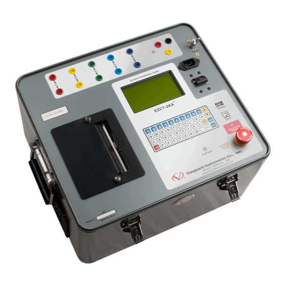
REV 1 EZCT-2000A Controls and Indicators The EZCT-2000A’s controls and indicators are shown in Figure 1 below. A leader line with an index number points to each control and indicator, which is cross-referenced to a functional description in Table 2. The table describes the function of each item on the control panel. The purpose of the controls and indicators may seem obvious, but users should become familiar with them before using the EZCT-2000A. -
Page 11: Table 2. Functional Descriptions Of Ezct-2000A Controls And Indicators
Functional Description Number Current transformer excitation voltage connectors. Each set of connectors contains a test voltage connector and sensing connector. The EZCT-2000A’s X X1, X2, X3, X4, X5 output terminals are rated to 2000 Vac working voltage. Any voltage above 2000 Vac will damage the input circuitry. -
Page 12: Pre-Test Setup
EZCT-2000A USER’S MANUAL REV 1 PRE-TEST SETUP Operating Voltages The EZCT-2000A’s operating voltage is preset at the factory for 100-120 Vac, 50/60 Hz or 200- 240 Vac, 50/60 Hz. LCD Screen Contrast Control [PAPER ∧ Contrast] To increase the LCD screen contrast, press and hold the key for two seconds. - Page 13 The thermal paper will show a red stripe to indicate that the roll is about to run out of paper. Computer Interface Ports The EZCT-2000A features one USB and one RS-232C PC interface port. A Windows-based “Current Transformer Analysis” software application is supplied with the EZCT-2000A. For further information, please see the EZCT-2000 Software User’s Manual.
-
Page 14: Operating Procedures
Always connect the EZCT-2000A to the substation ground before connecting any test cables. The EZCT-2000A is supplied with one 20-foot X cable set and one 35-foot H cable. The X cable connections are required to run the current transformer excitation test. The H and X cable connections are required to run the transformer turns-ratio test. -
Page 15: Figure 3. Bushing Ct Connection On Delta Transformer
REV 1 EZCT-2000A USER’S MANUAL Figure 3. Bushing CT Connection on Delta Transformer Figure 4. Bushing CT Connection on Y Transformer... -
Page 16: Ezct-2000A X Input Voltage Warning
300 Vac is applied to the X1-X2 terminals, a voltage of 2,364 Vac (300 Vac x 7.88) will be induced at the X1-X4 terminals. If all the test leads are connected to the EZCT-2000A and the excitation test is performed on the X1-X2 terminals, the voltage induced at the X1-X4 terminals will exceed 2,000 Vac as the voltage across the X1-X2 terminals increases above 250 Vac. -
Page 17: Performing Tests
REV 1 EZCT-2000A USER’S MANUAL Performing Tests 3.3.1. Entering Test Record Header Information You can enter the test record header information before performing tests. The record header includes identifying information such as the company, station, circuit, model number, etc. Once the header information has been entered, it will apply to all subsequent test records. - Page 18 EZCT-2000A USER’S MANUAL REV 1 d. The following screen will be displayed: STATION: ↑↓ TO POSITION "enter" to accept [ENTER] Type the station name using the alpha-numeric keypad and then press the key. e. The following screen will be displayed:...
- Page 19 REV 1 EZCT-2000A USER’S MANUAL h. The following screen will be displayed: SERIAL NUMBER: 27001 ↑↓ TO POSITION "enter" to accept [ENTER] Type the serial number using the alpha-numeric keypad and then press the key. i. The following screen will be displayed:...
-
Page 20: Performing Resistance, Excitation, And Ratio Tests
The following procedure describes the general steps for performing excitation, resistance, and ratio tests. a. When the EZCT-2000A is turned on, it will first go through a start-up cycle and load the firmware. Then the “START-UP” menu will be displayed as shown below: 1. - Page 21 REV 1 EZCT-2000A USER’S MANUAL e. If the selected test included an excitation test, the following screen will be displayed: SET TEST CURRENT: 1. 0.2A 2. 0.5A 3. 1A 4. 2A 5. 5A 6. 10A Select the maximum test current for the excitation test by pressing the corresponding key ( Most CT’s will saturate before the excitation current reaches 1A.
- Page 22 EZCT-2000A USER’S MANUAL REV 1 ENTER PLATE RATIO: ENTER PLATE RATIO: 1000 : 0.0 1000 : 5.0 [ENTER] Type the second number using the keypad and then press the key. Continue to step g. 2. NO Press the key if you do not want to enter the CT nameplate values. Continue to step g.
- Page 23 REV 1 EZCT-2000A USER’S MANUAL If you had selected a test current greater than 1 Amp in step e, the following screen will be displayed: NOTE SATURATION CUR WILL BE REDUCED TO 1 AMP. (PRESS ANY KEY...) Press any key to continue.
- Page 24 EZCT-2000A USER’S MANUAL REV 1 l. The following screen will be displayed showing a summary of the test parameters: TEST 1 parameters: 1200V 1.0A x1-x2 "START" to begin [START] Press the key to start the test. m. If the selected test included a resistance test, the following screen will be displayed...
- Page 25 (YES) if you would like to print the test results. The test results will be printed on the thermal printer. A typical EZCT-2000A tabulated test report printout is shown in Figure 6. Typical graphic reports are shown in Figure 7 and Figure 8.
- Page 26 EZCT-2000A USER’S MANUAL REV 1 q. The following screen will be displayed: TEST 1 SAVED Press any key to continue. r. The following screen will be displayed: RUN ANOTHER TEST? 1. YES 2. NO Press the key (NO). s. The following screen will be displayed: SAVE THIS RECORD? 1.
- Page 27 The following confirmation screen will then be displayed: RECORD NUMBER 1 has been saved! The test record number is automatically assigned to each test record stored in the EZCT-2000A’s Flash EEPROM. NOTE Press any key to return to the “START-UP” menu.
-
Page 28: Figure 6. Typical Ezct-2000A Tabulated Report Printout
EZCT-2000A USER’S MANUAL REV 1 Figure 6. Typical EZCT-2000A Tabulated Report Printout... -
Page 29: Table 3. Descriptions Of Tabulated Test Results Elements
Number Test record header information. The EZCT-2000A X terminals (taps) that were selected for this test. Test note for this particular test. The test note can be up to 20-characters long. Recorded excitation current readings on the CT secondary winding. -
Page 30: Figure 7. Typical Ezct-2000A Graphic Report
EZCT-2000A USER’S MANUAL REV 1 Knee Point Marker Figure 7. Typical EZCT-2000A Graphic Report Figure 8. Typical EZCT-2000A Graphic Report with Multiple Plot Curves... -
Page 31: Working With Test Records
3.4.1. Restoring and Printing a Test Record From Flash EEPROM You can restore a test record from the EZCT-2000A’s Flash EEPROM to the working memory. You can then print the restored test record on the unit’s built-in thermal printer. To restore a test record: a. - Page 32 EZCT-2000A USER’S MANUAL REV 1 1. INTERNAL STORAGE 2. THUMB DRIVE Press the key (INTERNAL STORAGE). The following screen will then be displayed: RESTORE RECORD 1. enter record number 2. scroll to select Continue with the steps below. ENTER RECORD NUMBER If you know the record number that you would like to restore, press the key.
- Page 33 REV 1 EZCT-2000A USER’S MANUAL The following screen will be displayed: RECORD RESTORED! PRINT RECORD? 1. YES 2. NO If you do not want to print the test record, press the key (NO). The test record will be restored to the working memory, and you will be returned to the “START- UP”...
- Page 34 EZCT-2000A USER’S MANUAL REV 1 Press any key to continue. The following screen will be displayed: RECORD RESTORED! PRINT RECORD? 1. YES 2. NO If you do not want to print the test record, press the key (NO). The test record will be restored to the working memory, and you will be returned to the “START-...
-
Page 35: Restoring And Printing A Test Record From A Usb Flash Drive
EZCT-2000A USER’S MANUAL 3.4.2. Restoring and Printing a Test Record From a USB Flash Drive You can restore a test record from a USB Flash drive to the EZCT-2000A’s working memory using the steps below: a. Make sure the USB Flash drive containing the test record(s) is inserted in the EZCT- 2000A’s USB Flash drive port (“USB MEM”... - Page 36 EZCT-2000A USER’S MANUAL REV 1 RESTORE THUMB DRIVE REC_ [ENTER] Type the record number that you would like to restore and press the key. If you do not know the record number, you can print a test record directory. Please see section 3.4.4 for details.
- Page 37 REV 1 EZCT-2000A USER’S MANUAL h. The following screen will be displayed: PRINT OPTIONS: 1. FULL DATA 2. ABBREVIATED data Press the key to print the full tabulated data and graphics results on the thermal printer. After printing is finished, you will be returned to the “START-UP” menu.
-
Page 38: Printing A Restored Test Record
EZCT-2000A USER’S MANUAL REV 1 3.4.3. Printing a Restored Test Record You can print a test record at the time that it is restored from the Flash EEPROM (see section 3.4.1), or you can restore it to the working memory and print it later. To print the current test record in the working memory: a. - Page 39 REV 1 EZCT-2000A USER’S MANUAL Press the key to print the tabulated data and graphics results on the thermal printer. The test record will be printed on the thermal printer and you will be returned to the “START-UP” menu. Press the key to print the test report and graphic results on the thermal printer, without the excitation voltage and current data points.
-
Page 40: Printing A Directory Of Test Records Stored In The Ezct-2000A's Memory
REV 1 3.4.4. Printing a Directory of Test Records Stored in the EZCT-2000A’s Memory You can print a directory of all the test records stored in the EZCT-2000A’s Flash EEPROM using the steps below: a. Start from the “START-UP” menu: 1. - Page 41 The short directory option prints the last 10 records stored in the EZCT-2000A’s Flash EEPROM. The short directory listing will be printed on the thermal printer and you will be...
-
Page 42: Figure 9. Typical Internal Test Record Directory Printout
EZCT-2000A USER’S MANUAL REV 1 Figure 9. Typical Internal Test Record Directory Printout... -
Page 43: Printing A Directory Of Test Records Stored In A Usb Flash Drive
You can print a directory of all the test records in a USB Flash drive using the steps below: a. Make sure the USB Flash drive is inserted in the EZCT-2000A’s USB Flash drive port (“USB MEM” port). Then start from the “START-UP” menu: 1. -
Page 44: Figure 10. Typical Usb Flash Drive Record Directory Printout
EZCT-2000A USER’S MANUAL REV 1 Figure 10. Typical USB Flash Drive Record Directory Printout... -
Page 45: Copying Test Records To A Usb Flash Drive
EZCT-2000A USER’S MANUAL 3.4.6. Copying Test Records to a USB Flash Drive You can easily copy test records stored in the EZCT-2000A’s Flash EEPROM to a connected USB Flash drive using the steps below: a. Make sure a USB Flash drive is inserted in the EZCT-2000A’s Flash drive port (“USB MEM”... - Page 46 1. COPY SINGLE RECORD Press the key (COPY SINGLE RECORD) if you would like to copy a single record from the EZCT-2000A to the USB Flash drive. The following screen will be displayed: ENTER RECORD NUMBER to copy to flash drv...
- Page 47 2. COPY ALL RECORDS Press the key (COPY ALL RECORDS) if you would like to copy all the test records from the EZCT-2000A to the USB Flash drive. The following screen will be displayed: SAving record 1 to thumb drive Please wait...
-
Page 48: Erasing Test Records From The Flash Eeprom
EZCT-2000A USER’S MANUAL REV 1 3.4.7. Erasing Test Records From the Flash EEPROM You can erase individual or all test records stored in the EZCT-2000A’s Flash EEPROM. To erase a test record: a. Start from the “START-UP” menu: 1. RUN TEST 02/16/10 2. - Page 49 REV 1 EZCT-2000A USER’S MANUAL ERASE RECORD 1. ERASE SINGLE REC. 2. ERASE ALL RECORDS Continue with the steps below: 1. ERASE SINGLE REC. Press the key if you would like to erase a single record. The following screen will be displayed:...
- Page 50 REV 1 2. ERASE ALL RECORDS Press the key if you would like to erase all of the test records stored in the EZCT-2000A’s flash EEPROM. The following confirmation screen will be displayed: ERASE ALL RECORDS! Are you sure? "ENTER" TO CONTINUE.
-
Page 51: Erasing Test Records From A Usb Flash Drive
You can erase individual or all test records stored in a USB Flash drive. To erase a test record: a. Make sure the USB Flash drive is inserted in the EZCT-2000A’s USB Flash drive port (“USB MEM” port). Then start from the “START-UP” menu: 1. - Page 52 EZCT-2000A USER’S MANUAL REV 1 d. The following screen will be displayed: ERASE RECORD 1. ERASE SINGLE REC. 2. ERASE ALL RECORDS "STOP" TO EXIT 1. ERASE SINGLE REC. Press the key (ERASE SINGLE REC.) if you would like to erase a single record.
- Page 53 REV 1 EZCT-2000A USER’S MANUAL 2. ERASE ALL RECORDS Press the key (ERASE ALL RECORDS) if you would like to erase all of the test records stored in the USB Flash drive. The following confirmation screen will be displayed: ERASE ALL THUMB DRIVE...
-
Page 54: Working With Test Plans
CT winding terminal combinations (X1 to X5) for each test. Up to 10 test definitions can be stored per test plan, and up to 128 CT test plans can be stored in the EZCT-2000A’s Flash EEPROM. The ability to use test plans makes CT testing an extremely simple process. To perform a test, the EZCT-2000A is connected to the CT terminals and a test plan is selected to run. - Page 55 The test plan will be extracted from the test record in the working memory and will be saved to the EZCT-2000A’s Flash EEPROM as a new test plan. The test plan number will be automatically incremented by the EZCT-2000A.
-
Page 56: Printing A Directory Of Test Plans Stored In The Ezct-2000A's Memory
REV 1 3.5.2. Printing a Directory of Test Plans Stored in the EZCT-2000A’s Memory You can print a directory of all the test plans stored in the EZCT-2000A’s Flash EEPROM using the steps below: a. Start from the “START-UP” menu: 1. -
Page 57: Figure 11. Typical Ezct-2000A Flash Eeprom Test Plan Directory Printout
EZCT-2000A USER’S MANUAL You will be automatically returned to the “START-UP” menu after the directory printing is finished. A typical Flash EEPROM test plan directory printout is shown in Figure 11 below. Figure 11. Typical EZCT-2000A Flash EEPROM Test Plan Directory Printout... -
Page 58: Printing A Directory Of Test Plans Stored In A Usb Flash Drive
3.5.3. Printing a Directory of Test Plans Stored in a USB Flash Drive. To print a directory of all the test plans stored in a USB Flash drive: a. Make sure the USB Flash drive is inserted in the EZCT-2000A’s Flash drive port (“USB MEM” port). Then start from the “START-UP” menu: 1. -
Page 59: Figure 12. Typical Usb Flash Drive Test Plan Directory Printout
REV 1 EZCT-2000A USER’S MANUAL Figure 12. Typical USB Flash Drive Test Plan Directory Printout... -
Page 60: Printing A Test Plan
EZCT-2000A USER’S MANUAL REV 1 3.5.4. Printing a Test Plan To print a test plan: a. Start from the “START-UP” menu: 1. RUN TEST 02/16/10 2. SETUP 10:24:25 3. TEST PLANS 4. DIAGNOSTIC Press the key (TEST PLANS). b. The following screen will be displayed: 1. -
Page 61: Table 4. Description Of Test Plan Elements
REV 1 EZCT-2000A USER’S MANUAL Figure 13. Typical Test Plan Printout Table 4. Description of Test Plan Elements Item Description Number Number of tests in test plan (2) Tests to be performed (Excitation and Turns Ratio) Terminals used for excitation test (X2-X3) Maximum excitation voltage (300 V) Maximum excitation current (2.0 A) -
Page 62: Erasing Test Plans From The Flash Eeprom
2. ERASE ALL PLANS The above screen will be displayed only if a USB Flash drive is NOT connected to the EZCT-2000A’s USB Flash drive port. If a USB Flash drive is connected, the following screen will be displayed: NOTE 1. - Page 63 REV 1 EZCT-2000A USER’S MANUAL ERASE TEST PLAN 1. ERASE SINGLE PLAN 2. ERASE ALL PLANS Continue with the steps below: 1. ERASE SINGLE PLAN Press the key if you would like to erase a single test plan. The following...
- Page 64 EZCT-2000A USER’S MANUAL REV 1 ERASE ALL PLANS! Are you sure? "ENTER" TO CONTINUE. [STOP] If you would like to cancel the erasure process, press the key. No test plans will be erased and you will be returned to the “START-UP” menu.
-
Page 65: Erasing Test Plans From A Usb Flash Drive
3.5.6. Erasing Test Plans From a USB Flash Drive To erase one or all test plans stored on a USB Flash drive: a. Make sure the USB Flash drive is inserted in the EZCT-2000A’s USB Flash drive port (“USB MEM” port). Then start from the “START-UP” menu: 1. - Page 66 EZCT-2000A USER’S MANUAL REV 1 1. ERASE SINGLE PLAN Press the key (ERASE SINGLE PLAN) if you would like to erase a single plan from the USB Flash drive. The following screen will be displayed: ERASE THUMB DRIVE PLAN_ [ENTER] Type the test plan number that you would like to erase and press the key.
- Page 67 REV 1 EZCT-2000A USER’S MANUAL ERASING all thumb drive test plans PLEASE WAIT... The following screen will be displayed after all of the test plans have been erased from the USB Flash drive: all thumb drive test plans erased! Press any key to return to the “START-UP” menu.
-
Page 68: Loading A Test Plan From The Ezct-2000A's Flash Eeprom
LOAD TEST PLAN NUMBER: The above screen will be displayed only if a USB Flash drive is NOT connected to the EZCT-2000A’s USB Flash drive port. If a USB Flash drive is connected, the following screen will be displayed: NOTE 1. - Page 69 REV 1 EZCT-2000A USER’S MANUAL LOAD TEST PLAN NUMBER: Continue with the steps below: [ENTER] Type the test plan number that you would like to load and press the key. If you do not know the test plan number, you can print a test plan directory using the instructions in section 3.5.2.
-
Page 70: Loading A Test Plan From A Usb Flash Drive
3.5.8. Loading a Test Plan from a USB Flash Drive To load a test plan from a USB Flash drive: a. Make sure the USB Flash drive is inserted in the EZCT-2000A’s USB Flash drive port (“USB MEM” port). Then start from the “START-UP” menu: 1. - Page 71 Press the key if you would like the loaded test plan to be also saved in the EZCT-2000A’s Flash EEPROM. Any existing test plans in the EZCT-2000A’s Flash EEPROM will not be over-written. The EZCT-2000A will automatically assign a new test plan number and store the test plan in the next available memory location.
-
Page 72: Running A Test Using A Loaded Test Plan
The following screen will be displayed: CABLES WILL BE ENERGIZED! "START" TO BEGIN [START] Press the key and the EZCT-2000A will start running the test per the test plan settings. The screen will be updated with the test status. - Page 73 REV 1 EZCT-2000A USER’S MANUAL When the test has finished, the following screen will be displayed: SAVE THIS RECORD? 1. YES 2. NO Press the key (YES) to save the record. The following screen will be displayed momentarily: SAVING RECORD...
- Page 74 "START" to begin [START] Press the key to begin the test. e. The EZCT-2000A will start performing the test per the test plan parameters. When the test has finished, the following screen will be displayed: ANY KEY TO CONTINUE =77.6 =0.3876...
- Page 75 REV 1 EZCT-2000A USER’S MANUAL g. The following screen will be displayed: KEEP THIS TEST? 1. YES 2. NO Press the key (YES) to keep the test results. h. The following screen will be displayed: TEST 2 SAVED Press any key to continue.
- Page 76 EZCT-2000A USER’S MANUAL REV 1 The following confirmation screen will then be displayed: RECORD NUMBER 2 has been saved! Press any key to return to the “START-UP” menu.
-
Page 77: Unloading A Test Plan From The Working Memory
REV 1 EZCT-2000A USER’S MANUAL 3.5.10. Unloading a Test Plan from the Working Memory To unload the test plan from the working memory and clear all the test plan parameters: a. Start from the “START-UP” menu: 1. RUN TEST 02/16/10 2. -
Page 78: Changing Setup Parameters
EZCT-2000A USER’S MANUAL REV 1 CHANGING SETUP PARAMETERS Setting the Knee Point Marker Use the steps below to change the knee point marker for the excitation graph: a. Start from the “START-UP” menu: 1. RUN TEST 02/16/10 2. SETUP 10:24:25 3. -
Page 79: Figure 14. Graphic Report Showing Knee Point Marker
REV 1 EZCT-2000A USER’S MANUAL d. The following screen will be displayed: 1. IEEE 30 DEGREE 2. IEEE 45 DEGREE 3. IEC 10%V-->50%I Press either the key (IEEE 30 DEGREE), the key (IEEE 45 DEGREE), or the (ASA 10%V-->50%I) to select the desired knee point marker. The knee point marker will be set and you will be returned to the “START-UP”... -
Page 80: Enabling And Disabling The Buried Ct In Transformer Delta Option
EZCT-2000A USER’S MANUAL REV 1 Enabling and Disabling the Buried CT in Transformer Delta Option 4.2.1. Enabling the Buried CT in Transformer Delta Option If you are measuring the turns ratio of a CT buried in the transformer Delta windings (see Figure 15 and Figure 16 for further information), you must first enable the “Buried CT in Delta”... -
Page 81: Disabling The Buried Ct In Transformer Delta Option
REV 1 EZCT-2000A USER’S MANUAL e. The following screen will be displayed: RATIOS WILL BE ADJUSTED by 2/3. ARE YOU SURE? 1. YES 2. NO Press the key (YES). f. The following screen will be displayed: -buried ct in delta- ratios adjusted by two-thirds. - Page 82 EZCT-2000A USER’S MANUAL REV 1 c. The following screen will be displayed: 1. SET TIME 2. buried ct in delta 3. knee point marker 4. print raw data Press the key (BURIED CT IN DELTA). d. The following screen will be displayed: 1.
-
Page 83: Figure 15. Buried Ct In A Delta Transformer Illustration 1
REV 1 EZCT-2000A USER’S MANUAL Figure 15. Buried CT in a Delta Transformer Illustration 1 Figure 16. Buried CT in a Delta Transformer Illustration 2... - Page 84 • The CT turns ratio is now measured as Ratio = or Ratio = ). This measured turns ratio is higher than the actual turns ratio. • The EZCT-2000A will display the correct CT turns ratio by adjusting the measured turns ratio by...
-
Page 85: Setting The Clock
REV 1 EZCT-2000A USER’S MANUAL Setting the Clock To set the EZCT-2000A’s internal clock: a. Start from the “START-UP” menu: 1. RUN TEST 02/16/10 2. SETUP 10:24:25 3. TEST PLANS 4. DIAGNOSTIC Press the key (SETUP). b. The following screen will be displayed: 1. - Page 86 REV 1 Printing Raw Memory Buffer Data You can print the raw data from the EZCT-2000A’s memory buffer for diagnostic purposes. This will print a table of current and voltage values stored in the unit’s working memory. To print the raw buffer data: a.
-
Page 87: Diagnostics, Verification, And Troubleshooting
REV 1 EZCT-2000A USER’S MANUAL DIAGNOSTICS, VERIFICATION, AND TROUBLESHOOTING Performing a Diagnostics Test The Diagnostics test mode displays the output voltage at the selected X leads (V ), the voltage sensed by the H leads (V ), and the X voltage excitation current (I ). - Page 88 EZCT-2000A USER’S MANUAL REV 1 d. The following screen will be displayed: caution! cables will be energized! "ENTER" to continue [ENTER] Press the key to continue. e. The following screen will be displayed and the V , and I values will be continuously...
-
Page 89: Verifying The Ezct-2000A's
Verifying the EZCT-2000A’s V Sense Circuit Using an External Meter The excitation voltage (V ) sensed by the EZCT-2000A can be verified using an external RMS volt meter. Follow the steps below to verify the EZCT-2000A’s V sense circuit: a. Connect the X cables to an RMS volt meter as shown in Figure 17. -
Page 90: Verifying The Ezct-2000A's I
You can verify the excitation current (I ) sensed by the EZCT-2000A by using an external RMS ampere meter. Follow the steps below to verify the EZCT-2000A’s I sense circuit: a. Connect the X cables to a power resistor and an RMS ampere meter as shown in Figure b. -
Page 91: Quickly Verifying The Ezct-2000A's Turns Ratio Circuit
Run a turns ratio test (see section 3.3.2). d. Observe the turns ratio test on the LCD screen. The turns ratio should be 1.000 since the excitation voltage is the same as the sensed voltage. Figure 19. EZCT-2000A Turns Ratio Verification Test Connections... -
Page 92: Troubleshooting Guide
The excitation current can be raised during a test. When running the • The EZCT-2000A X cable is driving an • Check the CT terminal connection. excitation test, the V opened circuit. voltage can be raised but the excitation current is always zero during a test. - Page 93 Fill out all required fields (marked with red labels) and then click on the “Firmware” checkbox to the right of the “EZCT-2000A” label. Then fill out the serial number field on the right. Click on the “Submit” button once all form fields have been filled out.
- Page 94 EZCT2A_M.hex. Copy this file to the root of a USB Flash drive. f. Make sure the EZCT-2000A’s power if OFF, and then insert the USB Flash drive containing the firmware file in the EZCT-2000A’s Flash drive interface port (“USB MEM”...
- Page 95 REV 1 EZCT-2000A USER’S MANUAL erasing BLoCK 4 loading code from flash drv. When the firmware upgrade has finished, the following screen will be displayed: loading code from flash drv. BOOT LDR R x.xx You will hear a series of beeps as the unit re-boots. Once the unit has re-booted, the “START-...
- Page 96 1520 S. Hellman Ave • Ontario, CA 91761 • USA Phone: 909-923-9390 • Fax: 909-923-9391 www.vanguard-instruments.com Copyright © 2010 by Vanguard Instruments Company, Inc. EZCT-2000A User’s Manual • Revision 1.0 • February 16, 2009 • TA...
Need help?
Do you have a question about the EZCT-2000A and is the answer not in the manual?
Questions and answers