
Related Manuals for Pack Leader PL-622


Summary of Contents for Pack Leader PL-622
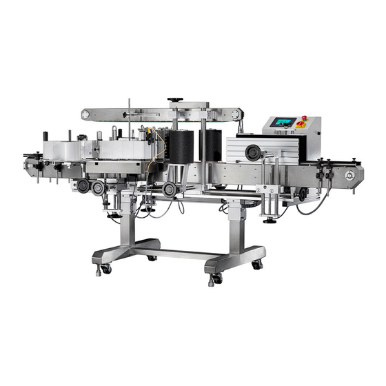
- Page 1 PL-622 FRONT AND BACK LABELER OPERATIONAL MANUAL Serial Number: Electricity: Φ...
-
Page 2: Table Of Contents
Table of Contents Title Page Machine Sub- Assemblies ..........................5 Machine Dimensions ............................6 Machine Features ............................8 Specification of Label Reel ..........................9 Safety Regulations ............................10 Label Applicator ............................11 Drive PU & Aluminum Roller Adjustments ....................13 Guide Rail .............................. - Page 3 Title Page Label Lead Fixed Assembly ........................... 43 Label Lead Assembly 2 ..........................44 Label Lead Assembly 3 ..........................45 Brush Set ..............................46 Label Peel Plate Assembly ..........................47 PU Roller Assembly ............................48 Lever Sleeve Assembly ..........................49 Base Paper Collect Assembly 1 ........................
- Page 4 Title Page Top Hold Down Cover Assembly ........................79 Servo Motor Assembly ..........................80 Sponge Roller Adjustment Assembly ......................81 Sponge Roller Assembly -1 ........................... 82 Sponge Roller Assembly -2 ........................... 83 Conveyor Assembly ............................84 Conveyor Assembly Part List ........................85 Conveyor Rear Side Plate Assembly ......................
-
Page 5: Machine Sub- Assemblies
PL-622 FRONT AND BACK LABELING MACHINE Machine Sub- Assemblies - 5 -... -
Page 6: Machine Dimensions
Machine Dimensions - 6 -... - Page 7 Machine Specification 1. VOLTAGE: 110V/220VAC 2. FREQUENCY: 50HZ/60HZ 3. PHASE: SINGLE 4. POWER CONSUMPTION: 900VA 5. Conveyor Width: 150mm 6. Speed Control: 8 speeds 7. Conveyor Max Speed: 30 M/Minute 8. Dispensing Max Speed: 30 M/Minute 9. Labeling Head Driver: Step Motor Drive 10.
-
Page 8: Machine Features
Machine Features The build-in operation manual in the system is very easy and well documented for any new trainee to follow. This system reduces the training time for the new operator and can learn to operate it within a few minutes. The build-in trouble-shooting feature reduces the repair time for system breakdown. -
Page 9: Specification Of Label Reel
Specification of Label Reel Base Paper Translucent Reel Inner Diameter: 76 mm Reel Outer Diameter: 370 mm Interval of Label Min. 3 mm (between label) Width of Base Paper Label Width + 4 mm Width of Label 150 H Label Head – 10 ~ 150 mm 200 H Label Head –... -
Page 10: Safety Regulations
Safety Regulations 1. Make sure the hands are dry before to put on the plug. Especially, in the food industries or in wet working environment Danger Safe 2. Do not put hands or fingers on the inner tube when adjust the height of the foot stand. Immediately lift up the conveyor if hands or fingers are trapped Safe Danger... -
Page 11: Label Applicator
Label Applicator To put the labels in the label applicator, kindly follow the following instructions with diagrams: Right applicator Left applicator 1 Put the roll of label on the tray and pass it through the tension roller so it will not spin out of control. 2 Fasten the tension clip after passing through this point to ensure tension on the label strip and avoid loose labels. - Page 12 6 The drive PU rubber roller pulls the base paper to position the labels. The aluminum pressure roller must be locked in place with the PU rubber roller in order to squeeze the paper and pull effectively. See C. Drive PU Roller Look Aluminum pressure roller...
-
Page 13: Drive Pu & Aluminum Roller Adjustments
Drive PU & Aluminum Roller Adjustments Step 1.Turn on the power. Then turn the Lever lever to make the aluminum roller in contact with the drive PU roller Step 2. Check the in between of the drive PU roller and the aluminum roller whether intact tightly or not (try to hold and rotate aluminum roller if intact tightly, proceed to step 4, if not proceed to step 3... -
Page 14: Guide Rail
Guide Rail Guide Rail: To guide the products in the right position or direction Adjustment lock Guide rail Right Warning If the guide rail’s width is not adjusted to conform with the object’s dimensions, this will affect the precision of the applied labels. So it is very important to adjust the guide rails according to the objects dimension. -
Page 15: Parts Adjustments
Parts Adjustments 1. Conveyor Adjustment: To adjust tightness of conveyor belt, loosen the two nuts on the screws. Turn CCW to loosen and CW to tighten. Make sure the conveyor is centered will be noisy if not centered. 2.Conveyor height adjustment: Loosen the fixed screws, adjust the conveyor to the appropriate height and tighten the screw again. - Page 16 4. In adjusting the side pressure’s roller chain, there are 2 places to adjust screw A. When adjusting A, the 2 screws must be adjusted evenly and must check if the degree of tightness is the same. Another thing to check is if the side pressure’s roller chains are level with each other. If the rollers are not level, the bottles will not be oriented properly.
- Page 17 6. Wrap around belt adjustment (optional function): To adjust the tightness and centering the belt, adjust the screw A. When adjusting, use only small increments and let the belt run for a while to determine the final position. A belt that is not centered will slip up or down.
-
Page 18: Label Sensor Adjustment
Label Sensor Adjustment 1. Please follow the direction of diagram to install the label sensor 2. Kindly place the label through the detect zone of label sensor 3. Adjust the sensitivity of label sensor to appropriate intensity after placing the label through the label sensor Sensitivity Adjust of Label Sensor 1. -
Page 19: Chain Aligner Station Adjustment
Chain Aligner Station Adjustment Chain aligner station’s purpose is to maintain the correct position of objects to be labeled on the conveyor belt. This also acts as a separator to maintain a fixed distance between objects to be labeled. Height adjustment wheel is used to adjust the height of the side pressure to accommodate different height of Power transmission set Sliding base... -
Page 20: Top Hold Down & Sponge Roller
Top Hold Down & & & & Sponge Roller When the bottle passes through the side pressure station its position is corrected and the top hold down will press it down for stable label application. It also holds the bottle for the sponge rollers to press the labels to a flat and even finish. -
Page 21: Top Hold Down Adjustment
Top Hold Down Adjustment 1. When adjusting the Top Hold Down, please put the bottle under the Top Hold Down, then adjust the up/down hand wheel until the top hold down presses upon the bottle just enough to hold it. This will maintain a stable labeling of the bottle. -
Page 22: Adjusting The Labeling Head And Bottle
Adjusting the labeling head and bottle A. First put the bottle on the conveyor belt and place the widest part of the bottle in between the dispenser. Check first if the bottle is on the center of the conveyor belt then adjust the dispenser to close in on the bottle until it is very close and does not hinder the passing of the bottle. - Page 23 C. The second bottle is labeled correctly. The third bottle misplaced to the right. The first bottle is misplaced on the left. In the First bottle loosen the object sensor and move it to the right until the label is applied on the right position.
-
Page 24: Machine Operation
Machine Operation Please follow the operation steps and instruction 1-1. Plug-in the appropriate power supply voltage 1-2. Turn of the power (Turn on the emergency stop switch if in “off” condition) Diagram 1 1-3. The display will shows as diagram 1. 1-4. - Page 25 Diagram 3 shows on display is label length set. 3-2, On the other hand, label length could be set by the numerical keypad below the “label length set’’ button; 3-3. Turn ‘CONVEYOR” and “LABEL” both ON to start labeling process after labeling length set. ※...
- Page 26 Diagram 4 4-2. Speed selection contains 8 levels of labeling speed. 4-3. Key in value in “Missing Label” for the sensor to detect missing label. 4-4. Turn ON the “Missing label” after key-in of the value in the Missing label set, await the diagram shows on display then function will start ※...
-
Page 27: Touch Screen
Touch Screen Do not bump or press heavily the screen Please lightly press any point inside the screen to key-in input data Please lightly press bottom with the finger to select Please use soft cleaner or wet cloth to clean the surface of the touch screen Operators are not advised to open the control box or power box to change any spare part. -
Page 28: Trouble Shooting
Trouble Shooting PROBLEM 1: LABEL LENGTH CAN NOT BE SET A: LABEL SENSOR WAS NOT ADJUSTED PROPERLY 1. Inspect the condition of label sensor. If the two lights (green & red) Are set properly, refer to “Sensitivity adjust instruction of label sensor” If label length still cannot be set, replace the label sensor or sensor box. - Page 29 Trouble shooting PROBLEM 5: LABEL WILL NOT STICK ON PRODUCT A. LABEL COMES OUT TOO LATE Slowly adjust the object sensor forward to dispensing plate until label is coming out on time. B. LABEL COMES OUT NOT SMOOTHLY Check whether the PU rubber (with a lock) in the label applicator is lock or not. If not, please kindly lock it.
-
Page 30: Electronic Diagram
Electronic Diagram - 30 -... -
Page 31: Control Box Frame
Control Box Frame - 31 -... -
Page 32: Electronic Parts List
Electronic Parts List DESCRIPTION PARTS NO. Power switch CQ1203KL6 C-1400 2-1 Emergency button I C-1403 2-2 Emergency button II C-1402 2-3 Emergency button III 51WR-800E15YE112 Delta Touch screen 2YBR-DOPB05S100 Switching Power Supply E-0070 EMI filter YC10T1(10A/250VAC) 2YXQF-10A250VAC 6-1 Fuse bracket C-1500 6-2 Fuse bracket plate C-1505... -
Page 33: Applicator Exploded View
Applicator Exploded View - 33 -... -
Page 34: Applicator Exploded Part List
Applicator Exploded Part List DESCRIPTION PART NO. QTY. NOTE Applicator base plate assembly Applicator back plate assembly Label peel plate assembly Fixed label lead assembly Label lead assembly 1 Label lead assembly 2 Label lead assembly 3 Lever sleeve assembly PU roller assembly Label press assembly Base paper collect assembly 1... -
Page 35: Applicator Exploded Part List
Applicator Exploded Part List DESCRIPTION PART NO. QTY. NOTE Philips Head Screws XNMW-M46 Socket Head Cap Screws M5*25 XNJW-M525 Washer M4 XNQC-M4 Spring washer M4 2FWO-M4 Socket Head Cap Screws M4*10 XNJW-M410 Washer M5 XNQC-M5 Bolt M4 XNAW-M310 Sensor box E-0090 Philips Head Screws M3*45 XNMW-M345... -
Page 36: Label Supply Plate Assembly
Label Supply Plate Assembly - 36 -... -
Page 37: Label Supply Plate Assembly Part List
Label Supply Plate Assembly Part List DESCRIPTION PART NO. QTY. NOTE Label supply board LA1-PL150-028 Bearing 7R8NR 5TGH-R8NR Bearing 6002zz 5TGH-6002zz Fixing spindle of tension bar LA1-PL150-031 S-ring S12 DCSV-S12 Tension bar LA1-PL150-035 bolt XNAW-M420 Brake belt LA1-PL150-090 Fixing shaft of brake belt LA1-PL150-036 Hexagon Socket Head Cap Screw XNJW-M510... -
Page 38: Tension Bar Assembly
Tension Bar Assembly DESCRIPTION PART NO. QTY. NOTE Pad of tension bar LA1-PL150-037 Roller shaft of tension bar LA1-PL150-097 E-ring E4 DCEV-E4 Interior roller of tension bar LA1-PL150-098 Sponge roller of tension bar LA1-PL150-099 Socket Head Cap Screws M4*70 XNJW-M470 - 38 -... -
Page 39: Applicator Base Plate Assembly
Applicator Base Plate Assembly DESCRIPTION PART NO. QTY. NOTE Applicator base plate LA1-PL150-001B Bearing 6202NR 5TGH-6202NR Bearing F688zz 5TGH-F688zz Upper Sleeve LA1-PL150-022 Bearing 7R8NR 5TGH-R8NR Applicator fixture LA1-PL150-003 Back cover fixing shaft LA1-PL150-027 Socket Head Cap Screws M5*16 XNJW-M516 Socket Head Cap Screws M4*16 XNJW-M416 - 39 -... -
Page 40: Applicator Back Plate Assembly
Applicator Back Plate Assembly DESCRIPTION PART NO. QTY. NOTE Applicator back plate LA1-PL150-002 Bearing 6002NR 5TGH-6002NR Bearing F688zz 5TGH-F688zz Bearing 6201NR 5TGH-6201NR Bottom sleeve LA1-PL150-023 Socket Head Cap Screws XNJW-M36 Spring washer 2FWO-M3 - 40 -... -
Page 41: Label Lead Assembly 1
Label Lead Assembly 1 DESCRIPTION PART NO. QTY. NOTE Label lead roller LA1-PL150-092 Bearing RI1212 5T5W-RI1212 Label lead roller shaft LA1-PL150-094 S-ring S12 DCSV-S12 Lower label roller sleeve – large LA1-PL150-019 Label position sleeve - large LA1-PL150-039 Spring LA1-PL150-052 - 41 -... -
Page 42: Label Press Assembly
Label Press Assembly DESCRIPTION PART NO. QTY. NOTE Label press plate base LA1-PL150-046 Label press plate LA1-PL150-047 Philips Head Screws XNMW-M36 Spring washer M3 2FWO-M3 Label press pad LA1-PL150-089 Knob 802020M410 51WR-802020M410 Label press shaft LA1-PL150-054 Spring base LA1-PL150-017 Spring LA1-PL150-016 Socket Head Cap Screws M4*10 XNJW-M410... -
Page 43: Label Lead Fixed Assembly
Label Lead Fixed Assembly DESCRIPTION PART NO. QTY. NOTE Label lead roller LA1-PL150-092 Inner sleeve ring LA1-PL150-021 Label lead roller shaft LA1-PL150-094 S-ring S12 DCSV-S12 Lower label roller sleeve –large LA1-PL150-019 Label position sleeve –large LA1-PL150-039 Spring LA1-PL150-052 - 43 -... -
Page 44: Label Lead Assembly 2
Label Lead Assembly 2 DESCRIPTION PART NO. QTY. NOTE Label lead roller LA1-PL150-092 Bearing RI1212 5T5W-RI1212 Label lead roller shaft LA1-PL150-093 S-ring S12 DCSV-S12 Lower label roller sleeve – large LA1-PL150-019 Label position sleeve –large LA1-PL150-039 Spring LA1-PL150-052 - 44 -... -
Page 45: Label Lead Assembly 3
Label Lead Assembly 3 DESCRIPTION PART NO. QTY. NOTE Label lead roller LA1-PL150-092 Bearing RI1212 5T5W-RI1212 Label lead roller shaft LA1-PL150-093 S-ring S12 DCSV-S12 Lower label roller sleeve – small LA1-PL150-020 Label position sleeve -small LA1-PL150-040 Spring LA1-PL150-052 - 45 -... -
Page 46: Brush Set
Brush Set DESCRIPTION PART NO. QTY. NOTE Label press tension bar LA1-PL150-071B Bearing R6NR 5TGH-R6NR Socket Head Cap Screws XNJW-M420 Hex Nuts M4 XAXR-M4 Brush fixing base LA1-PL150-074 Socket Head Cap Screws XNJW-M425 Spring LA1-PL150-091 Washer M5 XNQC-M5 Spring washer M5 2FWO-M5 Socket Head Cap Screws XNJW-M520... -
Page 47: Label Peel Plate Assembly
Label Peel Plate Assembly DESCRIPTION PART NO. QTY. NOTE Dispensing plate bottom base LA1-PL150-050 Support shaft LA1-PL150-060 Dispensing master shaft LA1-PL150-059 Dispensing plate upper base LA1-PL150-051 Dispensing plate LA1-PL150-069B Socket Head Cap Screws M4 XNJW-M416 Socket Head Cap Screws M5 XNJW-M516 Spring washer M5 2FWO-M5... -
Page 48: Pu Roller Assembly
PU Roller Assembly DESCRIPTION PART NO. QTY. NOTE PU roller shaft LA1-PL150-053B Double head round keys RGM-5545 Pulley LA1-PL150-006 Socket Set Screw XN5Z-M55 Pulley LA1-PL150-007 Socket Set Screw XN5Z-M510 - 48 -... -
Page 49: Lever Sleeve Assembly
Lever Sleeve Assembly DESCRIPTION PART NO. QTY. NOTE Bias shaft LA1-PL150-061 Bias wheel LA1-PL150-062 Bearing 6804zz 5TGH-6804zz S-ring S20 DCSV-S20 Position plate LA1-PL150-025 Spanner ring LA1-PL150-024 Socket Head Cap Screws XNJW-M410 Socket Set Screw XN5Z-M55 - 49 -... -
Page 50: Base Paper Collect Assembly 1
Base Paper Collect Assembly 1 DESCRIPTION PART NO. QTY. NOTE Base paper collect plate SB-10003-002 Collect plate power base SB-10003-001 Aluminum extrusion collect rod SB-10003-003B Socket Head Cap Screws XNJW-M620 Paper press rod SB-10003-004B Press plate PRO1000303-020B Screw LA1-PL150-102 Socket Set Screw XN5Z-M620 Socket Head Cap Screws XNJW-M516... -
Page 51: Base Paper Collect Assembly 2
Base Paper Collect Assembly 2 DESCRIPTION PART NO. QTY. NOTE Base paper collect transmission shaft LA1-PL150-013 Friction slice LA1-PL150-009 Brake pressing plate LA1-PL150-011 Double head round keys RGM-4425 Top pin LA1-PL150-012 Socket Set Screw XN5Z-M810 Spring LA1-PL150-026 Pulley LA1-PL150-008 Friction plate LA1-PL150-010 Bearing RI1212 5T5W-RI1212... -
Page 52: Applicator Motor Assembly
Applicator Motor Assembly DESCRIPTION PART NO. QTY. NOTE Motor SM286352576A A21R-SM286352576A XNJW-M516 Socket Head Cap Screws Spring washer 2FWO-M5 RGM-4425 Double head round keys XN5Z-M610 Socket Set Screw Pulley XL-25T-14-4 LA1-PL150-004 Motor spacer rod LA1-PRO-A1-007B XNJW-M525 Socket Head Cap Screws Washer XNQC-M5 - 52 -... -
Page 53: Applicator Adjustment -1
Applicator Adjustment -1 DESCRIPTION PART NO. QTY. NOTE Connecting shaft AA1-PL622-001B XNJW-M410 Socket Head Cap Screws Sliding shaft fixed plate AA1-PL501-008 Hand wheel QRGX-3043125B10 2FN2-101610 nylon washer XNJW-M512 Socket Head Cap Screws XNJW-M625 Socket Head Cap Screws Adjusting screw AA1-PL622-004 Applicator sliding base AA1-PL622-002 Sliding shaft... -
Page 54: Applicator Adjustment -2
Applicator Adjustment -2 DESCRIPTION PART NO. QTY. NOTE Applicator B sliding base AA1-PL622-002 Screw block AA1-PL501-003B Screw block AA1-PL501-017 Bearing LFB-3025 5TDU-LBF3025 Bearing LFB-2520 5TDU-LBF2520 Sliding shaft AA1-PL521-002 Sliding shaft fixed plate AA1-PL501-011 2FN2-101610 nylon washer Adjusting screw AA1-PL501-007 Hand wheel QRGX-3043125B10 XNJW-M512 Socket Head Cap Screws... -
Page 55: Applicator Adjustment -3
Applicator Adjustment -3 DESCRIPTION PART NO. QTY. NOTE Applicator A sliding base AA1-PL622-003 Screw block AA1-PL501-003B Bearing LFB-3025 5TDU-LBF3025 Bearing LFB-2520 5TDU-LBF2520 Sliding shaft AA1-PL521-002 Sliding shaft fixed plate AA1-PL501-011 2FN2-101610 nylon washer Adjusting screw AA1-PL501-007 Hand wheel QRGX-3043125B10 XNJW-M512 Socket Head Cap Screws XNJW-M625 Socket Head Cap Screws... -
Page 56: Chain Aligner Adjustment Assembly
Chain Aligner Adjustment Assembly DESCRIPTION PART NO. QTY. NOTE Transmission shaft AA1-PL622-205B S-ring S15 DCSV-S15 Pulley 20T T2Q2X-20XL050155 Timing belt 140XL-050 T2Q2-140XL050 Motor protect cover AA1-PL622-210 XNAW-M410 Philips Head Screws RGM-5525 Double head round keys Sliding shaft D25x 700L 512C-25D700L Chain aligner F/B adjustment assembly Connecting shaft AA1-PL622-001B... -
Page 57: Chain Aligner F/B Adjustment Assembly
Chain Aligner F/B Adjustment Assembly DESCRIPTION PART NO. QTY. NOTE Adjusting screw AA1-PL622-215 2FN2-101610 nylon washer Hand wheel QRGX-3043125B10 XNJW-M512 Socket Head Cap Screws Fixed base AA1-PL622-209 Protect jacket base AA1-PL622-211 XNJW-M416 Socket Head Cap Screws Bearing 6902zz 5TGH-6902zz XN5Z-M610 Socket Set Screw - 57 -... -
Page 58: Chain Aligner Motor Assembly
Chain Aligner Motor Assembly DESCRIPTION PART NO. QTY. NOTE Motor fixed plate AA1-PL622-208 Cover base AA1-PL622-211 Gear box MZ9G15B A2RG-MZ9G15B RGM-5525 Double head round keys Driving pulley T2Q2X-20XL005155 XN5Z-M55 Socket Set Screw Adjusting screw AA1-PL622-216 2FN2-101610 nylon washer Screw lengthening shaft AA1-PL622-202 XN5Z-M610 Socket Set Screw... -
Page 59: Bevel Gear Base Set-1
Bevel Gear Base Set-1 DESCRIPTION PART NO. QTY. NOTE Bevel gear adjusting base AA1-PL622-204 Screw block AA1-PL501-003B Bearing LFB-2520 5TDU-LBF2520 Bevel gear AA1-PL622-201 Bearing 6006zz 5TGH-6006ZZ S-ring S30 DCSV-S30 Prop pillar AA1-PL622-207 Transmission shaft AA1-PL622-206C Bearing 6004zz 5TGH-6004ZZ S-ring S20 DCSV-S20 RGM-4415 Double head round keys... -
Page 60: Bevel Gear Base Set-2
Bevel Gear Base Set-2 DESCRIPTION PART NO. QTY. NOTE Bevel gear adjusting base AA1-PL622-203 Screw block AA1-PL501-017 Bearing LFB-2520 5TDU-LBF2520 Bevel gear AA1-PL622-201 Bearing 6006zz 5TGH-6006ZZ S-ring S30 DCSV-S30 Prop pillar AA1-PL622-207 Transmission shaft AA1-PL622-206C Bearing 6004zz 5TGH-6004ZZ S-ring S20 DCSV-S20 RGM-4415 Double head round keys... -
Page 61: Chain Aligner Assembly - 1
Chain Aligner Assembly – 1 - 61 -... - Page 62 Chain Aligner Assembly – 1 Part List DESCRIPTION PART NO. QTY. NOTE SP2-PL622-010 Chain roller set Chain roller base set Connecting base SP1-PL622-009 Driven chain roller set -1 Driven chain roller set -2 Side pressure bottom cover SP1-PL622-013 Spacing shaft SP1-PL622-017B Chain aligner plate -1 SP1-PL622-007B...
-
Page 63: Chain Aligner Assembly - 2
Chain Aligner Assembly – 2 - 63 -... -
Page 64: Chain Aligner Assembly - 2 Part List
Chain Aligner Assembly – 2 Part List DESCRIPTION PART NO. QTY. NOTE SP2-PL622-010-1 Chain roller set Chain roller base set Connecting base SP1-PL622-009 Driven chain roller set -1 Driven chain roller set -2 Side pressure bottom cover SP1-PL622-013-1 Spacing shaft SP1-PL622-017B Chain aligner plate -1 SP1-PL622-006B... -
Page 65: Chain Roller Set
Chain Roller Set DESCRIPTION PART NO. QTY. NOTE Chain RS-35 T2XW-35SS Roller shaft SP1-PL622-025 Roller SP1-PL622-026 E-ring E2.5 DCEV-E2.5 Chain buckle 35SS T2RW-35SSCL - 65 -... -
Page 66: Chain Roller Base Set
Chain Roller Base Set DESCRIPTION PART NO. QTY. NOTE Lining plate fixed base SP1-PL622-014B Chain lining plate SP1-PL622-016 Elasticity plate set XNJW-M620 Socket Head Cap Screws XNJW-M620 Socket Head Cap Screws - 66 -... -
Page 67: Elasticity Plate Set
Elasticity Plate Set DESCRIPTION PART NO. QTY. NOTE Elasticity plate base SP1-PL622-022 Elasticity top plate SP1-PL622-023B Elasticity shaft SP1-PL622-011 XNJW-M516 Socket Head Cap Screws Spring SP1-PL622-012 - 67 -... -
Page 68: Driven Chain Roller Set -1
Driven Chain Roller Set -1 DESCRIPTION PART NO. QTY. NOTE Sprocket SP1-PL622-024 Driven wheel shaft SP1-PL622-020 Bearing 6902zz 5TGH-6902ZZ S-ring S15 DCSV-S15 - 68 -... -
Page 69: Driven Chain Roller Set -2
Driven Chain Roller Set -2 DESCRIPTION PART NO. QTY. NOTE Adjusting shaft SP1-PL622-019 Sprocket SP1-PL622-024 Bearing 6902zz 5TGH-6902ZZ S-ring S15 DCSV-S15 - 69 -... -
Page 70: Chain Aligner Sliding Base
Chain Aligner Sliding Base DESCRIPTION PART NO. QTY. NOTE Hand wheel fixed plate SP1-PL622-008 Adjusting screw SP1-PL622-002 Hand wheel 51CX-6020-50-M8 2FN2-8121.0T nylon washer XAXR-M8 Hex Nuts XNJW-M620 Socket Head Cap Screws Sliding shaft D20*180 512C-25D180 - 70 -... -
Page 71: Top Hold Down Adjustment Assembly
Top Hold Down Adjustment Assembly - 71 -... -
Page 72: Top Hold Down Adjustment Assembly Part List
Top Hold Down Adjustment Assembly Part List DESCRIPTION PART NO. QTY. NOTE Top hold down base AA1-PL622-401 XNJW-M845 Socket Head Cap Screws XN5Z-M66 Socket Set Screw Adjusting shaft AA1-PL622-405 AA1-PL622-411 Screw Adjusting screw AA1-PL622-410 Position pin AA1-PL622-412 Adjusting base AA1-PL622-404 Bearing 5TDU-LFB4020 2FN2-101610... -
Page 73: Top Hold Down A
Top Hold Down A NOTE DESCRIPTION PART NO. QTY. Top hold down roller assembly Top hold down driven plate assembly Top hold down driven pulley assembly Top hold down driving plate assembly Top Hold Down Driving Pulley Assembly Top hold down cover assembly Top hold down belt 1000Hx20mm TH01-PRO-030 Servo motor assembly... -
Page 74: Top Hold Down Roller Assembly
Top Hold Down Roller Assembly NOTE DESCRIPTION PART NO. QTY. Base plate TH01-PRO-004D Bearing 5TDU-LEB0808 Screw XN2E-D840-M611.25 Roller shaft TH01-PRO-001B Bearing 6200zz 5TGH-6200zz S-ring S10 DCSV-S10 Sleeve TH01-PRO-036B 2FN2-8121.0T nylon Bearing fixed plate TH01-PRO-041 Washer XNQC-M8 Spring TH01-PRO-008D - 74 -... -
Page 75: Top Hold Down Driven Plate Assembly
Top Hold Down Driven Plate Assembly NOTE DESCRIPTION PART NO. QTY. Driven plate -1 TH01-PRO-032C Connection plate TH01-PRO-034B Driven plate -2 TH01-PRO-033C Fixed bracket TH01-PRO-021B Pan head screws Hexagon XNAW-M616 Socket Head Cap Screws XNJW-M512 - 75 -... -
Page 76: Top Hold Down Driven Pulley Assembly
Top Hold Down Driven Pulley Assembly DESCRIPTION PART NO. QTY. NOTE Driven pulley TH01-PRO-005C Bearing 6002zz 5TGH-6002zz driven pulley shaft TH01-PRO-007B S-ring S15 DCSV-S15 - 76 -... - Page 77 Top Hold Down Driving Plate Assembly NOTE DESCRIPTION PART NO. QTY. Driving plate -1 TH01-PRO-027C Connection plate TH01-PRO-034B Driving plate -2 TH01-PRO-028C Bearing 6902NR 5TGH-6902NR Fixed bracket TH01-PRO-026B Socket Head Cap Screws XNJE-M510 Pan head screws Hexagon XNAW-M616 - 77 -...
-
Page 78: Top Hold Down Driving Pulley Assembly
Top Hold Down Driving Pulley Assembly DESCRIPTION PART NO. QTY. NOTE Driving pulley TH01-PRO-006C Driving pulley shaft TH01-PRO-014B Double head round keys RGM-5520 Socket Set Screw XN5Z-M510 S-ring S15 DCSV-S15 Double head round keys RGM-5525 - 78 -... -
Page 79: Top Hold Down Cover Assembly
Top Hold Down Cover Assembly DESCRIPTION PART NO. QTY. NOTE Outer side plate TH01-PRO-029C Inner side plate TH01-PRO-024C Driven pulley bottom plate TH01-PRO-039 Driving pulley bottom plate TH01-PRO-038B - 79 -... -
Page 80: Servo Motor Assembly
Servo Motor Assembly NOTE DESCRIPTION PART NO. QTY. Motor fixed plate TH01-PRO-013B Bearing 6002zz 5TGH-6002zz Pulley LA1-PL150-007 Belt 116XL-050 T2Q2-116XL050 Cover TH01-PRO-019 Pulley 20XL T2Q2X-20XL050124 Gear box A2RG-F002SG60L110 Servo motor A2NZ-MHMD042PS1 Motor fixed bracket TH01-PRO-016B Motor fixed rod TH01-PRO-040 - 80 -... -
Page 81: Sponge Roller Adjustment Assembly
Sponge Roller Adjustment Assembly DESCRIPTION PART NO. QTY. NOTE Connection shaft AA1-PL622-001B Socket Head Cap Screws XNJW-M410 Adjustment screw AA1-PL622-004 D30 Fixed plate AA1-PL622-308 Hand wheel QRGX-3043125B10 Socket Head Cap Screws XNJW-M512 Socket Head Cap Screws XNJW-M625 nylon washer 2FN2-101610 Adjusting screw AA1-PL622-005 Sliding shaft... -
Page 82: Sponge Roller Assembly -1
Sponge Roller Assembly -1 DESCRIPTION PART NO. QTY. NOTE Adjusting base AA1-PL622-306 Screw block AA1-PL501-017 Bearing LBF-3025 5TDU-LBF3025 Extension plate AA1-PL622-307B AA1-PL622-305 Sponge roller fixed plate Socket Head Cap Screws XNJW-M620 Extension plate AA1-PL622-309 Washer LA1-PL200-017 Sponge roller spindle AA1-PL622-303 Sponge roller tube AA1-PL622-301 Sponge roller cover... -
Page 83: Sponge Roller Assembly -2
Sponge Roller Assembly -2 DESCRIPTION PART NO. QTY. NOTE Adjusting base AA1-PL622-306 Screw block AA1-PL501-003B Bearing LBF-3025 5TDU-LBF3025 Extension plate AA1-PL622-307B AA1-PL622-305 Sponge roller fixed plate Socket Head Cap Screws XNJW-M620 Extension plate AA1-PL622-309 Washer LA1-PL200-017 Sponge roller spindle AA1-PL622-303 Sponge roller tube AA1-PL622-301 Sponge roller cover... -
Page 84: Conveyor Assembly
Conveyor Assembly - 84 -... -
Page 85: Conveyor Assembly Part List
Conveyor Assembly Part List DESCRIPTION PART NO. QTY. NOTE Conveyor rear side plate assembly Conveyor front side plate assembly Conveyor driving pulley assembly S-ring S25 DCSV-S25 Conveyor driven pulley assembly Spacing bar CV1-PL501-011 Conveyor sliding gear CV1-PL501-007 Spring washer 2FWO-M616 Socket Head Cap Screws XNJW-M616 Conveyor motor assembly... -
Page 86: Conveyor Rear Side Plate Assembly
Conveyor Rear Side Plate Assembly - 86 -... -
Page 87: Conveyor Rear Side Plate Assembly Part List
Conveyor Rear Side Plate Assembly Part List DESCRIPTION PART NO. QTY. NOTE Conveyor rear side plate CV1-PL622-001 Spring washer 2FWO-M6 Hex Nuts XAXR-M6 Socket Head Cap Screws XNJW-M625 Socket Head Cap Screws XNJW-M516 Spring washer 2FWO-M5 Hex Nuts XAXR-M5 Conveyor master bearing sleeve CV1-PL501-006 Bearing 6905zz 5TGH-6905ZZ... -
Page 88: Conveyor Front Side Plate Assembly
Conveyor Front Side Plate Assembly - 88 -... -
Page 89: Conveyor Front Side Plate Assembly Part List
Conveyor Front Side Plate Assembly Part List DESCRIPTION PART NO. QTY. NOTE Conveyor side plate CV1-PL622-002 Spring washer 2FWO-M6 Hex Nuts XAXR-M6 Socket Head Cap Screws XNJW-M625 Socket Head Cap Screws XNJW-M516 Spring washer 2FWO-M5 Hex Nuts XAXR-M5 Conveyor master bearing sleeve CV1-PL501-006 Bearing 6905zz 5TGH-6905ZZ... -
Page 90: Conveyor Driving Pulley Assembly
Conveyor Driving Pulley Assembly DESCRIPTION PART NO. QTY. NOTE Driving pulley shaft CV1-PL622-006 Conveyor driving pulley T2GE-3820-19TD25 S-ring S25 DCSV-S25 Double head round keys RGM-8745 Double head round keys RGM-8715 - 90 -... -
Page 91: Conveyor Driven Pulley Assembly
Conveyor Driven Pulley Assembly DESCRIPTION PART NO. QTY. NOTE Conveyor driven pulley shaft CV1-PL501-012 Conveyor driven pulley T2GE-5820-19TD25 S-ring S25 DCSV-S25 - 91 -... -
Page 92: Conveyor Motor Assembly
Conveyor Motor Assembly - 92 -... -
Page 93: Conveyor Motor Assembly Part List
Conveyor Motor Assembly Part List DESCRIPTION PART NO. QTY. NOTE Motor fixed pillar CV1-PL521-022 Conveyor motor base CV1-PL521-017 Conveyor gear cover CV1-PL622-004 Encoder Set Conveyor servant pulley T2Q2X-14L050155 Pulley CV1-PL622-012 Pulley T2Q2X-24L05025B Motor M9MZ90GK4YG A2EU-M9MZ90GK4YG Gear box MZ9G15B A2RG-MZ9G15B Spring washer 2FWO-M6 Socket Head Cap Screws XNJW-M6130... -
Page 94: Encoder Set
Encoder Set DESCRIPTION PART NO. QTY. NOTE Encoder fixture CV1-PL622-010B Bearing LF-1910 5TGH-LF1910 Encoder transmittal shaft CV1-PL622-007 pulley T2Q2X-23XL03710 Encoder fixed pillar CV1-PL622-013 coupling 2YE2-BPC-66 Encoder CB-1000HC(1000pulse) 2YE2-CB1000 Encoder fixed base CV1-PL622-008 S-ring S10 DCSV-S10 Socket Head Cap Screws XNJW-M310 Spring washer 2FWO-M4 Socket Head Cap Screws... -
Page 95: Guide Rail A01
Guide Rail A01 DESCRIPTION PART NO. QTY. NOTE Adjustment pillar of guide rail 51CX-K-PIN-150 Hexagon head set screw XNKW-M816 Washer M8 XNQC-M8 Adjustment bar of guide rail GR1-PL501-002 Knob 51WR-606025M615 Up & down adjustment pillar 51CX-K-UB-160 Socket Set Screw XN5Z-M66 Guide rail GR1-PL622-001 - 95 -... -
Page 96: Guide Rail A02
Guide Rail A02 DESCRIPTION PART NO. QTY. NOTE Guide rail GR1-PL622-002 Adjustment pillar of guide rail 51CX-K-PIN-150 Hexagon head set screw XNKW-M816 Washer M8 XNQC-M8 Adjustment bar of guide rail GR1-PL501-002 Knob 51WR-606025M615 Socket Set Screw XN5Z-M66 Up & down adjustment pillar 51CX-K-UB-160 - 96 -... -
Page 97: Conveyor Base Plate Assembly
Conveyor Base Plate Assembly DESCRIPTION PART NO. QTY. NOTE Conveyor base FT1-PL622-002C Sliding shaft fixed base FT1-PL622-005 Socket Head Cap Screws XNJW-M625 Socket Set Screw XN5Z-M610 Sliding shaft 512C-30D1800L Two-way adjusting base FT1-PL622-003 Sleeve ring FT1-PL622-004 Bearing LFB-3025 5TDU-LBF3025 Sleeve 515W-30H704 Shaft binding base FT1-PL622-007B... -
Page 98: Foot Stand
Foot Stand DESCRIPTION PART NO. QTY. NOTE Foot stand FT1-PL622-001 Caster 51RX-2R25 Hexagon head set screw XNKW-M816 Fixed bolt for foot stand FT1-PL501-009 Nut for foot stand FT1-PL501-008 Tube coupler FT1-PL501-006 Tube coupler FT1-PL501-005 Socket Head Cap Screws XNJW-M825 Conveyor base fixed set FT1-PL501-002C Socket Head Cap Screws XNJW-M820... - Page 99 PACK LEADER USA 3951 East 137th Terrace Grandview, MO 64030 Phone: 816.581.4330 Fax: 816.581.4338 Email: sales@packleaderusa.com www.packleaderusa.com - 99 -...
Need help?
Do you have a question about the PL-622 and is the answer not in the manual?
Questions and answers