
Related Manuals for Acom 500S


Summary of Contents for Acom 500S
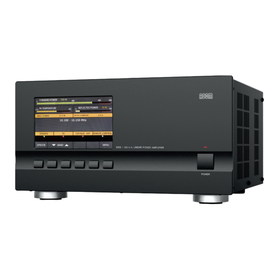
- Page 1 ACOM 500S 160-4 m Linear Power Amplifier User's Manual Installation, Operation and Maintenance OUTSTANDING HF POWER PRODUCTS March 2023...
- Page 2 User's Manual | ACOM 500S | 160-4 m Linear Power Amplifier This manual is for electronic distribution mainly. If you have it on paper and you no longer need it, please, recycle it! The latest versions of our User's Manuals are available at www.acom-bg.com...
-
Page 3: About Documentation
ACOM products and services. Further, this User's Manual is provided AS IS and ACOM shall not be liable for possible errors contained herein. - Page 4 User's Manual | ACOM 500S | 160-4 m Linear Power Amplifier Title of Documentation ACOM 500S 160-4 m Linear Power Amplifier User's Manual Installation, Operation and Maintenance Type of Documentation User's Manual Purpose of Documentation This manual explains Installation, Operation and Maintenance of the ACOM 500S 160-4 m Linear Power Amplifier.
-
Page 5: Table Of Contents
User's Manual | ACOM 500S | 160-4 m Linear Power Amplifier Contents ABOUT DOCUMENTATION ..........................3 GENERAL INFORMATION ........................... 8 1.1. Introduction and Description ......................8 1.2. Product History and Documentation Validity ................. 9 1.3. To the Reader of this Manual ......................9 1.4. - Page 6 User's Manual | ACOM 500S | 160-4 m Linear Power Amplifier 4.5. Automatic Protection System ....................... 39 MENUS - SETTINGS AND OPTIONS ......................41 5.1. Menu AMP MEASURE (Amplifier Measurements) ................ 42 5.2. Menu AMP SERVICE (Amplifier Service Functions) ............... 43 5.3.
- Page 7 Figure 4-2 | ACOM 06AT antenna tuner and switch (shown near 500S amplifier) ........37 Figure 4-3 | ACOM 500S amplifier screen with ACOM 04AT or 06AT antenna tuner installed ...... 38 Figure 4-4 | Appearance of an alarm message ....................39 Figure 5-1 | MENU SELECTION ........................
-
Page 8: General Information
Congratulations on purchasing one of the finest solid-state 160-4 m linear amplifiers in the world today. ACOM is pleased that you have chosen one of our products, and we will endeavor to provide you with the information and support you need to enjoy your purchase for many years. -
Page 9: Product History And Documentation Validity
1.2. The ACOM 500S amplifier serial production started in February 2023. This manual refers to the ACOM 500S amplifiers and describes the operating possibilities of all amplifiers produced till the publishing date of this manual. This manual is valid till a new manual is issued. -
Page 10: Additional Documentation
If assistance is needed, you should contact your local dealer first. If necessary, your dealer will contact ACOM for additional guidance. If you still have an issue you need to discuss with one of ACOM's specialists, the contact information is as follows: ACOM Ltd. -
Page 11: Product Identification
User's Manual | ACOM 500S | 160-4 m Linear Power Amplifier Product Identification 1.6. Every ACOM product features an ID (identification) label/plate. On this label, you can find data identifying the device. Which product identification data are important? Model designation - The model designation is the name of the device;... -
Page 12: Features
1.8. Easy to operate • The overall operation of ACOM 500S is extremely simplified: the screen menus are intuitive and easy to follow, and no special skill is required from the operator when changing frequency bands. User-friendly automatic control •... -
Page 13: Safety Considerations, Explicit Definitions
Safety Considerations, Explicit Definitions 1.9. The ACOM 500S linear amplifier is a Safety Class I unit regarding protection against electric shock. The third grounding lead of its mains cord (which is colored yellow with two green stripes) and the ground stud on the... - Page 14 User's Manual | ACOM 500S | 160-4 m Linear Power Amplifier Information notes described below apply to this User's Manual: These notes highlight operating procedures or practices that may improve equipment reliability and/or personnel performance, or to emphasize a concept.
- Page 15 User's Manual | ACOM 500S | 160-4 m Linear Power Amplifier PRECAUTIONS: DANGER Both the mains voltage and the high DC voltage up to 500 V inside the ACOM 500S amplifier are LETHAL! For your safety, pull the amplifier power plug out of the mains wall outlet and WAIT AT LEAST 3 minutes EACH TIME BEFORE you remove the cover of the amplifier.
-
Page 16: Installation
User's Manual | ACOM 500S | 160-4 m Linear Power Amplifier 2. INSTALLATION Unpacking and Initial Inspection 2.1. Before you install your amplifier, thoroughly read this manual. First, carefully inspect the cardboard carton and its contents for physical damage. ACOM ships amplifiers in highly protected containers, but it cannot assure that mistreatment by shippers will not occur. -
Page 17: Figure 2-2 | Acom 500S Packaged In A Cardboard Box
User's Manual | ACOM 500S | 160-4 m Linear Power Amplifier Take out the amplifier using handles of the middle secure element (see Figure 2-2 | ACOM 500S • , Pos. 4); packaged in a cardboard box Take out the amplifier (Pos. 8) from the middle secure element and remove top, bottom and •... -
Page 18: Line Voltage Selection
Power Factor Corrected (PFC) and inrush limited. This makes the operation from unstable mains and generators easy and trouble free. Thanks to the built-in SMPS, the ACOM 500S has no mains line voltage selector to take care of! Amplifier Location Selection 2.3. -
Page 19: Connections
User's Manual | ACOM 500S | 160-4 m Linear Power Amplifier Connections 2.4. Please, see Figure 2-3 | Rear panel - Connections Connection to your station must be accomplished in the order described below, before you apply mains voltage to the amplifier. -
Page 20: Figure 2-3 | Rear Panel - Connections
User's Manual | ACOM 500S | 160-4 m Linear Power Amplifier Figure 2-3 | Rear panel - Connections Figure 2-3 | Rear panel - Connections GND stud First, connect the wing-nut grounding stud of the amplifier (on the rear panel, marked GND) to the station's grounding system (see , Pos. - Page 21 , Pos. (c)) of the amplifier. Figure 2-3 | Rear panel - Connections ACOM 500S will operate normally with KEY OUT unconnected if your transceiver has no such input. Transceiver producers give different names to this input and they are for instance TX-INHIBIT, MUTE, LINEAR, etc.
- Page 22 (especially multi-band trap antennas). The RF OUTPUT 1 provides seamless integration with the auto-switching antenna tuners ACOM 04AT and ACOM 06AT, for access from amplifier's front panel to 4 antennas having an SWR up to 3, in the 160 to 6 meter bands.
- Page 23 User's Manual | ACOM 500S | 160-4 m Linear Power Amplifier Main fuses Please, see , Pos. (g). Figure 2-3 | Rear panel - Connections NOTICE Make sure you check whether the main fuses installed in your amplifier correspond to your local mains nominal voltage.
-
Page 24: Connecting To External Devices (Transceiver, Computer, Etc.) And User Settings
Figure 5-4 | Menu CAT/AUX SETTINGS Most of the modern transceivers can be connected by CAT to the ACOM 500S. This will allow the amplifier to track the transceiver frequency without any transmission and change the bands automatically when in OPERATE mode. -
Page 25: Table 2-1 | Signals And Pin Out Of The Cat/Aux Connector
User's Manual | ACOM 500S | 160-4 m Linear Power Amplifier Table 2-1 | Signals and pin out of the CAT/AUX connector CAT/AUX Pin Nr. Pin name Description Specification interface Receive Data TTL input Receive Data RS-232 input Transmit Data... -
Page 26: First Power-On, Control System, And Initial Check
User's Manual | ACOM 500S | 160-4 m Linear Power Amplifier 3. FIRST POWER-ON, CONTROL SYSTEM, AND INITIAL CHECK NOTICE Do not turn the amplifier on for at least 2 hours after unpacking it in the room where it will be used. Pay particular attention when you move it from a very cold into a warm place - condensation is likely and this could result in damage to the high voltage circuits. -
Page 27: Front Panel
User's Manual | ACOM 500S | 160-4 m Linear Power Amplifier Front Panel 3.2. POWER button Please, see (Pos. (a)). Figure 3-1 | Front panel - Controls and Readouts When the rear panel mains switch is turned on, push and hold for 1-2 seconds to start the amplifier up. When the amplifier is turned on, push to turn it off (back to Low Energy standby mode). -
Page 28: Basic Screen
User's Manual | ACOM 500S | 160-4 m Linear Power Amplifier Basic Screen 3.4. The following information areas are to be distinguished on the basic screen: Information area for the frequency band Please, see , Pos. (a). Figure 3-2 | Basic screen The edges of the currently selected BAND are displayed. -
Page 29: Control System - Buttons And Menus
• ascending or descending order. When ACOM 04AT tuner is assigned, BAND buttons are called SEGMENT and change the tuner frequency segments (see Section 4.4 Operation with an External Antenna Tuner March 2023... -
Page 30: Menu Button
Check of RF bypass path of a non-driven amplifier When the ACOM 500S is powered off, there is a bypass only from RF INPUT to RF OUTPUT 2, i.e., the RF OUTPUT 1 is disconnected and cannot be tested. - Page 31 Make sure that the amplifier is in STAND-BY mode. Push the OPR/STB button if needed to change to STB. In the USER PREFERENCES menu, unassign the ACOM tuner (if connected) in order to select the RF OUTPUT 2 where the antenna was connected at the previous test (above point (a)).
- Page 32 User's Manual | ACOM 500S | 160-4 m Linear Power Amplifier RX mode must change to TX; • The reflected power must read below 20 W; • The forward power must read between 20 and 150 W with minimum drive power from the •...
- Page 33 User's Manual | ACOM 500S | 160-4 m Linear Power Amplifier In case you use asymmetric antennas (GP and similar) install as many radials as practical (use • a well-developed counterpoise system); Add current chokes on the coaxial feeders; •...
-
Page 34: Operation
User's Manual | ACOM 500S | 160-4 m Linear Power Amplifier 4. OPERATION Change of Modes RX/TX and OPERATE/STANDBY; AUTO OPERATE User Setting 4.1. STANDBY mode In STANDBY mode, as well as when the amplifier is not powered, the transceiver's RF power is not amplified, the control KEY IN input does not affect the operation, and the KEY OUT output (see Section 2.4.c) KEY OUT... -
Page 35: Band Change, Standard And Expanded Frequency Coverage
User's Manual | ACOM 500S | 160-4 m Linear Power Amplifier AUTO OPERATE user setting AUTO OPERATE user setting can be turned on/off by the operator in the USER PREFERENCES menu (see Section ) or by a remote control 5.4 Menu USER PREFERENCES Figure 5-5 | Menu USER PREFERENCES command. -
Page 36: Antenna Change
4.4 Operation with an External Antenna Tuner If you do not have an ACOM tuner with Switch available, then the connector RF OUTPUT 2 is to be used for all bands and antennas. You may change antennas manually by either... -
Page 37: Operation With An External Antenna Tuner
The ACOM 04AT can be installed both in the shack and in a remote location (even out in the open, close to the antennas). It can be distanced up to 100 m (330 ft) from the amplifier, using a single coaxial cable. -
Page 38: Figure 4-3 | Acom 500S Amplifier Screen With Acom 04At Or 06At Antenna Tuner Installed
User's Manual | ACOM 500S | 160-4 m Linear Power Amplifier The connection of ACOM 04AT or 06AT tuner will make accessible specific features on the amplifier display that provide a transparent operation by following frequency and antenna selection changes in less than 50 ms. -
Page 39: Automatic Protection System
User's Manual | ACOM 500S | 160-4 m Linear Power Amplifier Automatic Protection System 4.5. The ACOM 500S control unit (see Section ) keeps track of 7.4 Using the Fault Codes (signatures) for Diagnostics most amplifier analogue and logic signals in all modes. - Page 40 User's Manual | ACOM 500S | 160-4 m Linear Power Amplifier Second protection level - SOFT FAULT The second protection level is a SOFT FAULT - when a value exceeded the safe level, but does not put the amplifier in a danger of a failure.
-
Page 41: Menus - Settings And Options
User's Manual | ACOM 500S | 160-4 m Linear Power Amplifier 5. MENUS - SETTINGS AND OPTIONS By pushing the MENU button (the rightmost on ) the user invokes the MENU Figure 3-2 | Basic screen SELECTION screen (see ). Each menu can be selected by the... -
Page 42: Menu Amp Measure (Amplifier Measurements)
User's Manual | ACOM 500S | 160-4 m Linear Power Amplifier Menu AMP MEASURE (Amplifier Measurements) 5.1. The menu AMP MEASURE (see is accessible from the MENU SELECTION Figure 5-2 | Menu AMP MEASURE screen (see ) in all modes. Here you can constantly monitor the values of 11 Figure 5-1 | MENU SELECTION parameters. -
Page 43: Menu Amp Service (Amplifier Service Functions)
User's Manual | ACOM 500S | 160-4 m Linear Power Amplifier Menu AMP SERVICE (Amplifier Service Functions) 5.2. The amplifier service menu (see ) is accessible from the MENU SELECTION Figure 5-3 | Menu AMP SERVICE screen (see ) at RX mode only. -
Page 44: Menu Cat/Aux Settings (Selection Of Cat/Aux Interface)
User's Manual | ACOM 500S | 160-4 m Linear Power Amplifier Menu CAT/AUX SETTINGS (Selection of CAT/AUX interface) 5.3. After a CAT cable is connected to both the transceiver and amplifier, the correct settings for the transceiver have to be entered via this menu. If there is no CAT connection, OFF has to be selected as INTERFACE type. - Page 45 Table 5-1 | Transceiver interface Under CAT interface control, the amplifier follows the VFO "A" frequency changes only. The ACOM 04AT and 06AT automatic antenna tuners follow the frequency of the amplifier. If your transceiver has more than one VFO, as well as in SPLIT mode, use VFO "A" for transmission and for tuner control.
-
Page 46: Menu User Preferences
Figure 5-5 | Menu USER PREFERENCES ANTENNA TUNER/SWITCH INSTALLED If ACOM 04AT or 06AT antenna tuner is connected to RF OUTPUT 1, select YES. See Section 4.4 Operation with and Refer to ACOM 04AT or 06AT User's Manual (available for download at an External Antenna Tuner www.acom-bg.com... -
Page 47: Menu Faults Log
User's Manual | ACOM 500S | 160-4 m Linear Power Amplifier Use the SELECT and SELECT buttons (left or right arrows) to select the character position. The ITEM and ITEM buttons (up and down arrows) change the characters. Finish by moving the pointer out of the editable fields by means of the SELECT (left arrow) button. -
Page 48: Menu Restore Default Settings
User's Manual | ACOM 500S | 160-4 m Linear Power Amplifier Menu RESTORE DEFAULT SETTINGS 5.6. Four different factory-reset levels are available (see Figure 5-7 | Menu RESTORE DEFAULT SETTINGS In order to confirm the selected action, the operator must push the ACTION (down arrow) button once more (as YES confirmation). -
Page 49: Remote Control
Remote control of ACOM 500S via the Internet is provided by the ACOM eBox Ethernet Remote Control device. The operation of ACOM 500S with ACOM eBox will be described in future editions of the ACOM eBox User's Manual. -
Page 50: Maintenance
7. MAINTENANCE DANGER Both the mains voltage and the high DC voltage up to 500 V inside the ACOM 500S amplifier are LETHAL! For your safety, pull the amplifier power plug out of the mains wall outlet and WAIT AT LEAST 3 minutes EACH TIME BEFORE you remove the cover of the amplifier. -
Page 51: Fuse Replacement
User's Manual | ACOM 500S | 160-4 m Linear Power Amplifier Fuse Replacement 7.3. DANGER If replacement of fuses is necessary, first pull out the amplifier mains plug from the mains outlet and wait for at least 3 minutes! NOTICE For replacement, only use standard fuses from the types recommended below. -
Page 52: Using The Fault Codes (Signatures) For Diagnostics
The data can be read in a plain-text format with a computer, using a standard terminal emulating program (TTY). You can send the recorded file to your dealer or to ACOM accordingly. To decode the downloaded hexadecimal data, you have to use the ACOM Hard Faults Signatures Converter (Excel file), distributed by ACOM free of charge. -
Page 53: Firmware
FAULTS LOG you undertake any action. When ACOM issues a new firmware version, the user can upload it in the amplifier after he checks the compatibility. When compatibility is confirmed a return to an earlier version is also possible. 7.5.3. Firmware Updates... -
Page 54: Figure 7-1 | Acom Terminal S Screenshot
Apply mains power, turn the amplifier on, and put it in STB mode. Exit all programs running on the computer and start ACOM Terminal S software. Select the desired COM port via menu Tools/Settings/Serial Port tab, and set it to 9600 8N1 (default settings for communication with amplifier's main firmware). - Page 55 If a firmware update/backup is unsuccessful check the connection cable, COM port settings, and try again. If the backup times out you will have to Disconnect and Connect the ACOM Terminal S in order to initiate the backup sequence again!
-
Page 56: Specifications
User's Manual | ACOM 500S | 160-4 m Linear Power Amplifier 8. SPECIFICATIONS Parameters 8.1. Standard Frequency Coverage 1.800 - 2.000 MHz (160 m band) 3.500 - 4.000 MHz (80 m band) 5.020 - 5.455 MHz (60 m band) 7.000 - 7.300 MHz (40 m band) 10.100 - 10.150 MHz... - Page 57 RF OUTPUT 2 - A well-matched antenna with an SWR below 1.5 can be connected to this output for any band. While low SWR is good for any band, it is extremely important on 6 and 4 m. RF OUTPUT 2 is not intended for ACOM 04AT or ACOM 06AT antenna tuners;...
-
Page 58: Functions
Remote control through ACOM eBox Ethernet Remote Control device (function in development) or via RS-232 interface Remote POWER ON by DSR/DTR and CTS/RTS lines on the RS-232 port or by ACOM eBox Ethernet Remote Control device (function in development) Remote POWER ON / TURN OFF by DC voltage impulse or continuous DC voltage on CAT/AUX port ON_RMT input Protection against relay switching under RF power (hot switching). -
Page 59: Regulatory Requirements
User's Manual | ACOM 500S | 160-4 m Linear Power Amplifier Regulatory Requirements 8.3. European conformity CE mark (Conformitè Europëenne) This symbol explains that "CE" marked ACOM product meets the essential requirements of the Radio Equipment Directive, 2014/53/EU, and the restriction of the use of certain hazardous substances in electrical and electronic equipment Directive, 2011/65/EU. - Page 60 User's Manual | ACOM 500S | 160-4 m Linear Power Amplifier RF Exposure Information WARNING Using the ACOM 500S amplifier, antennas must be operated at certain minimum distance between the radiator and any person's body. To comply with CFR Title 47 Part 97.13(C) and the Guidelines and Limits for Human...
-
Page 61: Storage And Shipment
User's Manual | ACOM 500S | 160-4 m Linear Power Amplifier Storage and Shipment 8.4. 8.4.1. Storage Environment The amplifier may be kept packed in a dry, ventilated and unheated location (with no chemically active substances such as acids or alkalis) within the following environment ranges:... -
Page 62: Returning To The Service Provider
User's Manual | ACOM 500S | 160-4 m Linear Power Amplifier 8.4.4. Returning to the Service Provider This document section contains the general information on packing and shipping an amplifier for diagnostics and repair. NOTICE Should it be necessary to ship the amplifier, use the original packing as described below. -
Page 63: Information On Disposing And Recycling Of Old Electrical And Electronic Equipment
User's Manual | ACOM 500S | 160-4 m Linear Power Amplifier Basic shipping insurance is provided by the customer when sending in an amplifier - you can verify the amount covered by the shipping company by looking on their website. If you are shipping the amplifier, full/upgraded coverage is available as a suggested option. -
Page 64: Notes
User's Manual | ACOM 500S | 160-4 m Linear Power Amplifier NOTES ……………………………………………………………………………………………………………..…………………………………………………………………………………………………………………….. ……………………………………………………………………………………………………………..…………………………………………………………………………………………………………………….. ……………………………………………………………………………………………………………..…………………………………………………………………………………………………………………….. ……………………………………………………………………………………………………………..…………………………………………………………………………………………………………………….. ……………………………………………………………………………………………………………..…………………………………………………………………………………………………………………….. ……………………………………………………………………………………………………………..…………………………………………………………………………………………………………………….. ……………………………………………………………………………………………………………..…………………………………………………………………………………………………………………….. ……………………………………………………………………………………………………………..…………………………………………………………………………………………………………………….. ……………………………………………………………………………………………………………..…………………………………………………………………………………………………………………….. ……………………………………………………………………………………………………………..…………………………………………………………………………………………………………………….. ……………………………………………………………………………………………………………..…………………………………………………………………………………………………………………….. ……………………………………………………………………………………………………………..…………………………………………………………………………………………………………………….. ……………………………………………………………………………………………………………..…………………………………………………………………………………………………………………….. ……………………………………………………………………………………………………………..…………………………………………………………………………………………………………………….. ……………………………………………………………………………………………………………..…………………………………………………………………………………………………………………….. ……………………………………………………………………………………………………………..…………………………………………………………………………………………………………………….. ……………………………………………………………………………………………………………..…………………………………………………………………………………………………………………….. ……………………………………………………………………………………………………………..…………………………………………………………………………………………………………………….. ……………………………………………………………………………………………………………..…………………………………………………………………………………………………………………….. ……………………………………………………………………………………………………………..…………………………………………………………………………………………………………………….. ……………………………………………………………………………………………………………..…………………………………………………………………………………………………………………….. ……………………………………………………………………………………………………………..…………………………………………………………………………………………………………………….. Page 64 of 66 | S e c t i o n NOTES... - Page 65 User's Manual | ACOM 500S | 160-4 m Linear Power Amplifier This manual is for electronic distribution mainly. If you have it on paper and you no longer need it, please, recycle it! The latest versions of our User's Manuals are available at www.acom-bg.com...
- Page 66 о о support@acom-bg.com ACOM and the ACOM logo are registered trademarks of ACOM Ltd. in many countries, www.acom-bg.com including the EU and United States. I The used images are illustrative only. Subject to change without notice. I Printed in Bulgaria.
Need help?
Do you have a question about the 500S and is the answer not in the manual?
Questions and answers