Advertisement
Quick Links
Important before assembly:
Read these instructions carefully before assembling or using the product.
Please check the contents of the boxes before attempting to assemble this product. The instructions will
have a checklist of parts and fittings.
Assemble the product as close to its intended final location/room as possible.
Health & Safety:
This product or some parts of this product will be heavy. Please use an assistant when lifting.
Please keep small parts out of reach of children.
Always use on a level, even surface.
DO NOT jump on the product or any of its parts.
DO NOT use this product if any parts are missing, damaged or worn.
DO NOT use this product unless all fixings are secured.
Further instructions are on the following pages.
Please keep these instructions for future reference.
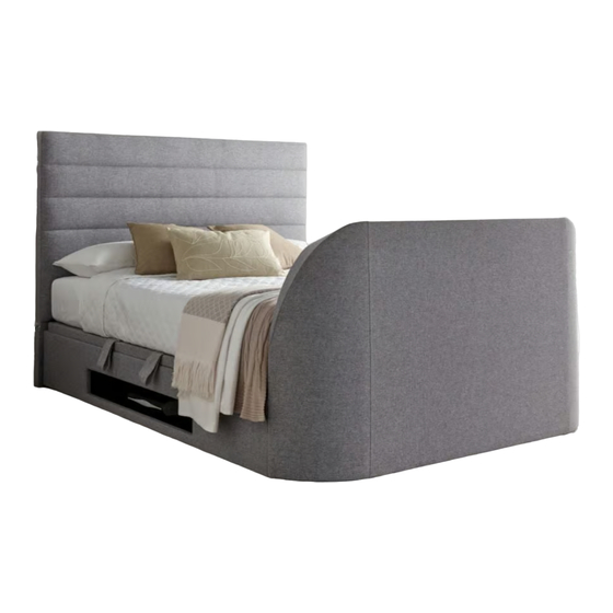
Appleby Ottoman TV Bed
Assembly Instructions
.
.
www.happybeds.co.uk
Advertisement

Related Manuals for Happy Beds Appleby Ottoman TV Bed


Summary of Contents for Happy Beds Appleby Ottoman TV Bed
- Page 1 Appleby Ottoman TV Bed Assembly Instructions Important before assembly: Read these instructions carefully before assembling or using the product. Please check the contents of the boxes before attempting to assemble this product. The instructions will have a checklist of parts and fittings.
- Page 2 These tools are not necessary, but may help to assemble the product. Do NOT use any power tools as this may damage the frame. (Not metal) This product or some parts of this product will be heavy. Please use an assistant when lifting. Never drag or push the pieces across a hard or stone floor as this will cause damage to the joints.
- Page 3 Components of Carton 1 (A) Footboard x 1 TV Mechanism Hardware Box pre-fixed in the foot end o-o-��eee 0® = o-��888 0® "" Component of Carton 2 (B) Side Rail-1 x 1 (C) Side Rail-2 x 1 (D) Head End Panel x 1 (E) Bottom Cross Rail (Long) x 1 (F) Bottom Cross Rail (Short) x 2 Hardware...
- Page 4 Hardware List {in Carton 1) (P) MS x 18mm (0) M8x25mm x 6 (Pre-Installed) x 10 (Pre-Installed) � Hardware List {in Carton 2) (S) Strap Handle (T) MS x 13mm (R) 3 X 40 X 86mm (Q) #8 X 1-1/4" X 16 (t)mmmu- �...
- Page 5 Step 1 • Before assembly please decide which side you require the "DVD / Media Compartment "Part C" side rail with opening will need to be placed at that side • Loosen the bolts located in the chosen head end. (Note: only loosen the bolts Do NOT remove them.) •...
- Page 6 Step 2 • Carefully remove the foot end from carton 1, remove the Hardware Box and all extra transportation packaging from inside. • To do this you will need to gently lay the foot end on it's back. Before doing so please ensure the area is completely free of anything that may cause damage or press into the fabric.
- Page 7 Step 3-1 • Carefully lift the foot end back to it's upright position. • Loosen the bolts located in the foot end. • Please note these should only be loosened and NOT removed. • Hook the side rail brackets over the bolts on both sides. Step 3-2 •...
- Page 8 Step 4 • Attach the rubber stopper {AB) with bolt and washer {AC) to the foot end & head end panel using screwdriver {Y) provided as shown. • The rubber stopper must be fixed to follow the lift base opening side as shown below.
- Page 9 Step 5 • Installing Batteries in the TV mechanism Wireless Remote Control. (AAA) Batteries x 2pcs (provided) install to battery case. Battery: Size: AAA- 010.5 X T44.5mm Caution: May explode or leak if recharged, inserted improperly, mixed Spec.: 1.5V with different battery types. Do not open battery. Dispose of used batteries promptly.
- Page 10 Step 7 • Continually press the "UP" switch on the wireless remote control, which will then lift the TV mechanism up until the footboard TV lid opens to its full extent. Continually press the "DOWN" switch on the wireless remote control to lower the TV mechanism. •...
- Page 11 Step 8 • TV cable connection plan. Make sure you have all the relevant cable connections required ( HDMI cable, TV Aerial cable, TV power cable, Optical cable etc ... ) before you install the TV. • The cable management holes are provided in the TV Tray to help you manage the cable's to keep them tidy and free from snags.
- Page 12 Step 9 • To adjust the TV tray to suit the height of your TV (without stand). Please follow step below 9.1 : Measure and make a note of the height (without stand!). 9.2 : Use the Allen key (20) to slightly loosen the up/down adjuster bolts-half turn only, do not remove all. (Please refer diagram below) 9.3 : Slide "the TV vertical bar up/down, while using the measure line matching the noted measurement height of your TV.
- Page 13 Step 10 • You are now ready to install your TV. • Raise the mechanism to it's highest position. • While standing behind your television (on the outside end of the footboard). - 'Facing the headboard' • Carefully place the TV on top of the two rubber TV mounting pedestals - ensuring the Gooseneck arm is perfectly inline with the 'centre' of the TV.
- Page 14 Step 12 • Connect all relevant cables to the TV. Note: For illustration purposes only, TV cables may vary. (Provided with your chosen headboard) Note: For illustration purposes only, TV cables may vary. YOUR TELEVISION REAR VIEW HDMI CABLE PLUG POSITION POSSIBLE SCNARIO'S Attention Please Note : Connecting Your HDMI or Aerial Cable as shown in diagram (X) can seriously Damage Your TV sockets.
- Page 15 Step 13 • Detail connection plan. WALL , ---------------------------------------------------- 7 -i- --- - HEADBOARD ---------- ----------------------------------------- WALL SOCKET "O >- - <( � □- >� � e __J � �o � I• ----7 �I <( L------c:::J- TV Lift Mechanism Television Cable Management holes Note: Please ensure you thread the relevant TV connection cables through the provided holes in the TV Tray - please avoid crossing cables across the rear of the TV lift mechanism area.
- Page 16 HOLES DETAIL FOR FIXING LIFT UP MECHANISM DOUBLE BED • • LEFT SIDE LIFT UP • • FOR DOUBLE BED (VIEW ON FOOT END) ..------------------------- • • RIGHT SIDE LIFT UP • • FOR DOUBLE BED (VIEW ON FOOT END) KING BED •...
- Page 17 Step 14 • Take out the bolt and washer from head and foot ends. • Attach the lift up mechanism using the bolt and washer. LAND@...
- Page 18 Step 15 • Attach the gas spring to the lift up mechanism using the nylon nut. correct incorrect correct incorrect FULLY TIGHTEN ALL NUTS AFTER ATTACHING THE PISTONS.
- Page 19 Step 16 • Take out the all the screw and washer from lift base (J) as shown. • For lift base (K), the last screw should be extend out 10mm as shown. The rest of screws & washers need to take out. Step 17 •...
- Page 20 Step 18 • First put the back lift base 'K' on top of lift up mechanism 'L' and 'M' with the provided Screws (AD) pre-installed as per step 16 to the first hole for safety and to prevent the lift base from dropping down. •...
- Page 21 Step 19 • Attach the bottom cross rail (long) (E) & bottom cross rail (short) (F) to the headboard, footboard and side rail as shown. Being careful! not to catch the fabric. • Attach the bottom cross rail (long) (E) to the side rail (B & C) and the bottom cross rail (short) X2 pcs (F) to the head end panel (D) and footboard (A) as shown (STEP 19.1 ),(STEP 19.2) &...
- Page 22 Step 20 • Place the base panel (G-1) & (I) on top of the bottom cross rail. • Put the base panel (I) to the foot end as shown. • Make sure the base panel with 90 degree angle was placed next to the side rail 'B'. •...
- Page 23 Step 21 • Attach the lift base (J) on lift up mechanism using screw and washer as shown. (Provided with your chosen headboard) UNDERNEATH VIEW...
- Page 24 Step 22 • Attach the metal plate (R) to the bottom of lift base (J) & (K) with screw (Q) as shown. (Provided with your chosen headboard) I-----<: :1---------"""": UNDERNEATH VIEW...
- Page 25 Step 23 • Place the base panel (G-2) & (H) on top of the bottom cross rail. • Put the base panel (H) to the foot end as shown. • Make sure the base panel with 90 degree angle was placed next to the side rail 'C'. •...
- Page 26 Step 24 • Attach the remote control pocket to the left or the right side rail as preferred. (Provided with your chosen headboard} Remote Control Pocket Remote TV Mechanism Control Wireless Remote Pocket Control...
- Page 27 Step 25 • Attach the mattress before operating the lift base. MATTRESS (Provided with your chosen headboard) This Lift Mechanism provides assistance with the lift of the mattress fitted to the base - it does not lift the mattress for you. The system has been designed to effectively lift the base system fitted with a variety of mattress weights and combinations of depth.
- Page 28 Step 26 • Make sure the bed frame 4 side angles are at 90 degrees before you closing the lift base. RIGHT LEFT Step 27 • The mattress must be fitted on the lift base. (Do not operate the lift up mechanism without the mattress fitted on the lift base.) •...
-
Page 29: Troubleshooting
TROUBLE SHOOTING TV LIFT DOES NOT OPERATE CHECK AC POWER ADAPTOR POWER CABLE (13) IS PLUGGED INTO A WORKING "SWITCHED ON" MAINS POWER SUPPLY. THE OTHER END OF POWER ADAPTOR CABLE (11) IS PLUGGED FIRMLY INTO THE TV LIFT POWER CABLE. -
Page 30: Part Description
G4 TV LIFT MECHANISM- OPTI-SERVE SPARE PARTS LIST ®------4 &-@ --.::Ja �f= � � � o--® o-----@ � � � � 0---@ ©--@ @--@ o----@ ()a---@ 8---@ o------- o-m----- o---@ o------@ ITEM NO. PART DESCRIPTION IV CODES Main TV-lift up mechanism (pre- assemble) TV-linear actuator G4 (pre-fixed) Actuator mounting top spacer (2pcs) (pre-fixed) IV001281... -
Page 31: General Care And Maintenance
Please dispose of all packaging safely. General Care & Maintenance Wipe clean with a slightly damp cloth. Avoid the use of all household cleaners and abrasives. Periodically check all screw & fixings to ensure they are secure. When moving your product, carefully lift into place. Never drag or push the product across the floor as this will cause damage to the joints.
Need help?
Do you have a question about the Appleby Ottoman TV Bed and is the answer not in the manual?
Questions and answers
Hi We have lost our remote control for our bed Part number iv001302
To obtain a replacement remote control for the Happy Beds Appleby Ottoman TV Bed, you should contact customer service. Visit: https://www.happybeds.co.uk/customer-service.
This answer is automatically generated