
Related Manuals for Sigma Controls MYRIAD DPC


Summary of Contents for Sigma Controls MYRIAD DPC
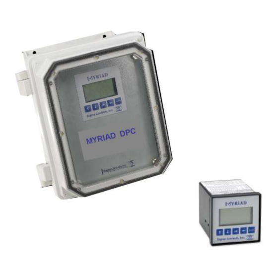
- Page 1 MYRIAD ‘DPC’ DUPLEX PUMP CONTROLLER INSTRUCTION MANUAL VERSION 3.9 VISIT OUR WEBSITE SIGMACONTROLS.COM MYRIAD DPC MANUAL 071122...
-
Page 2: Table Of Contents
TABLE OF CONTENTS INTRODUCTION Ordering Information Specifications Features WIRING DETAIL Dwg # 17-105 Analog Input Analog Output Digital Input Digital Output PROGRAMMING AND INITIAL SETUP Input Range Selection Terminal Block Detail Initial Setup & Programming Overview/Key Description MAINTENANCE & TROUBLESHOOTING DIAGNOSTICS APPENDIX ‘A’... -
Page 3: Introduction
INTRODUCTION: The Sigma Myriad DPC (Duplex Pump Controller) is a state of the art microprocessor based, user configurable instrument for the monitoring and control of two (2) constant speed or (2) variable speed driven pumps. The Myriad DPC performs all of the functions found in a full size control panel. -
Page 4: Specifications
SPECIFICATIONS: ANALOG INPUT (1 ea.) (A second AI is available when backup sensor is enabled) Analog, 4/20MA, 0-5V, 1-5V, 0-10VDC, isolated with common negative, +-0.1% accuracy. DIGITAL INPUTS (7 ea.) (7 additional DIs are available with the Aux PCB) Digital 10-30VDC ANALOG OUTPUT: (4 ea.) Analog, with common negative 0-20MA, 4/20MA, 0-5V, 0-10V (voltage output requires a resistor). - Page 5 FRONT PANEL: Gasketed Nema 4X ACCESS: (DIN CASE) Chassis & boards remove from front of case. TERMINAL STRIP: (40) Removable for ease of wiring 28 – 16 AWG CONNECTIONS: Removable screw terminal blocks 28 – 16 AWG wire. CONTROL OUTPUTS: 4 relay outputs, user programmable, SPDT Form ‘C’...
-
Page 6: Features
FEATURES: Microprocessor Based Graphic LCD Display 5 Function Keys Isolated 24VDC Sensor Power 4/20MA, 1-5V, 0-5V, 0-10VDC Programmable input 2 Analog Input 4 Analog Outputs 7 Digital Inputs (7 additional DIs are available with the Aux PCB) 4 Digital Outputs (Horn output available on Aux PCB) 4 Form ‘C’... - Page 9 PROGRAMMING & SETUP The Myriad DPC utilizes ‘plain English’ menu driven setup screens which are intuitive and easily understood. Alarm Indicator Level Indicator Process Value Pump Run Indicator Engineering Units MAIN DISPLAY NOTE: To ‘RETURN’ to the main display from any other screen, scroll to ‘EXIT’ and press ‘ENTER’.
- Page 10 MENU 2 SCALE Use the → ← buttons to highlight ‘SCALE’ and press ‘ENTER’. Use the ↑ ↓ arrow buttons to select the desired analog input range. NOTE: INPUT TYPE MUST BE COORDINATED WITH INPUT SELECTOR SWITCH LOCATED ON THE BOTTOM OF THE CIRCUIT BOARD (See Appendix ‘A’) The ‘DPC’...
- Page 11 INPUT SCALING TO ENGINEERING UNITS NOTE: This screen sets what the Myriad DPC displays in the main display for the selected input. The example shown above will display 0.0 units when the input is 4.00 MA. Both the input and the display at that input can be changed for different requirements.
-
Page 12: Analog Output
This screen allows the selection of several engineering units. With the cursor on the default value as shown, press the ↑ ↓ buttons to select between: FEET INCHES DEG. F DEG C FLOATS ING HG Use the ↑ ↓ buttons to select the desired engineering units then with the → ← buttons, highlight ‘NEXT’... - Page 13 SPEED SCALE The ‘level’ value will be highlighted, use the ↑ ↓ buttons to change the level point at which the speed of the drive (selected in the next block) is requested. In the example above, the drive will be at 50% speed when the level is 30 inches. Select a value of drive speed and level as described above and scroll to ‘EXIT’...
- Page 14 SETUP NOTE: The ‘SETUP’ menu allows access to the following items: 1) Pump elapsed timer 1 2) Pump elapsed timer 2 3) Trend screen time base 4) Password 5) Date 6) Alarm Horn on/off 7) Set MODBUS 8) Backup Sensor 9) Alarm Outputs 10) PID Enable ELAPSED TIMER 1 &...
- Page 15 CHANGE PASSWORD SCREEN Once the password has been changed make sure a record of the new password is retained. Access to the programming menus requires a correct password. Use the ↑ ↓ keys to enter a number up to 9999, select ‘NEXT’ and press ‘ENTER’ to enter the ‘change clock’...
- Page 16 Allows the MODBUS comm port to be set to match network requirements. Exit to save, then cycle Power to adopt new node. High and low level alarms are available on Relay 3. If desired this selection will provide high level alarm on RLY #3 and low level alarm on digital output #4.
- Page 17 Select 'REVERSE' to drive the output down when the process value exceeds the setpoint, as in pressure boosting applications. Select 'FORWARD' to drive the output up when the process value exceeds the setpoint. Select 'DUPLEX' for two pump operation Select 'SIMPLEX' when pump 2 is not installed. The Auxiliary PCB is a factory installed option.
- Page 18 When float control is enabled it serves as a backup control to the analog level sensing. This setting controls at what point the floats assume control. Select LEAD FLOAT to initiate backup control when the float above the low float is tipped. Used when the top 3 floats are hanging above the normal pumping range.
- Page 19 Following the procedure above, select a level value at which the lead pump turns off. Use ‘NEXT’ with the 'ENTER' button to access the: LAG PUMP ON SCREEN Select a value which turns on the lag pump. Use ‘NEXT’ and ‘ENTER’ to access the: LAG PUMP OFF SCREEN Again, select a level value which turns off the lag pump.
- Page 20 Change pump off delay as described above and select ‘NEXT’ and press ‘ENTER’ to advance to the: LEVEL ALARM SCREENS The next screens are as follows: Low Level Alarm Set Point Low Level Alarm Reset Point High Level Alarm Set Point High Level Alarm Reset Point Alarm Timer (This function controls the timing for alarms to be detected) Adjust and advance through the alarm settings as described previously.
- Page 21 NOTE: In this menu item, all alarm screens will be shown in an automatically ‘SCROLLING’ fashion. The following alarm status will appear on the screen: P1 Failed to Run P2 Failed to Run P1 Critical Alarm P2 Critical Alarm Seal Leak Alarm High Level Alarm Low Level Alarm Sensor Failure...
- Page 22 From the main menu press ‘ENTER’ key to access the ‘ENTER PASSWORD’ screen. Use the → ← buttons to scroll to the ‘VIEW’ position and press ‘ENTER’. NOTE: IT IS NOT NECESSARY TO ENTER A PASSWORD TO ENTER THIS SCREEN. VIEW MENU ‘TREND’...
- Page 23 MAINTENANCE AND TROUBLE SHOOTING MAINTENANCE: The Myriad DPC is a digital solid state device which requires no periodic maintenance. Occasional physical checks of the unit should be carried out for physical and mechanical security of mounting, terminal blocks, and electrical wiring.
- Page 24 20.00 MA and the output is 20.00 MA. These values can provide help in determining if the Myriad DPC is receiving the correct analog input. The next indicators are the digital input/output status. Any active (ON) DO/DI is indicated by an active, black, block above its respective number.
-
Page 25: Digital Input
Raw output at speed output #1 (AOI) DIGITAL DIGITAL INPUT Pump 1 Run Feedback Pump 2 Run Feedback Critical Alarm Pump 1 Critical Alarm Pump 2 Pump 1 HOA in Auto Pump 2 HOA in Auto Seal Leak Pump 1 & 2 3AI (see SETUP for other options) DIGITAL OUTPUT Relay 1 Run to Pump 1... - Page 26 PUMP ALARMS (1) Pump fail, after a pump has been ‘called’ to run a digital input (normally from the auxiliary contact on the respective motor starter) is ‘feedback’ to the controller at 1DI and 2DI. If the controller fails to see this input it assumes the motor starter has failed to energize the starter and it energizes the ‘Pump Failed to Run’...
- Page 27 APPENDIX ‘A’ SWITCH SELECTION OF ANALOG INPUT RANGES (Factory default 4/20MA). The range dip switches are located on the bottom of the main circuit board. Disconnect power, remove two rear screws, remove terminal strips, and slide the entire unit out of its case. Turn the unit upside down to locate the range dip switches.
-
Page 28: Dpc Addendum
APPENDIX ‘B’ DPC ADDENDUM VERSION 1.9 The intention of this addendum is to point out the differences between the Myriad DPC Manual (written for DPC V1.8) and the V1.9 upgrades. 1. The Real-time clock can be stopped if static or surges occur. Now it has an automatic reset so that if it stops it will restart in 60 seconds. - Page 29 APPENDIX ‘C’ AUXILIARY PCB ADDENDUM VERSION 4.0 The auxiliary PCB option adds standardized inputs and outputs to the DPC controller. These are some of the most commonly requested custom programming functions. This PCB is hard soldered at the factory. It is not user serviceable. Its existence is indicated by a 10 pin terminal on the back of the controller.
- Page 30 Float Control; Terminal #4 is for a normally open ’low‘ or ‘off’ float. It can be used to unlatch the lead and lag pumps or as a low water cutoff to redundantly protect a pump from running dry. Terminal #5 is for a normally open lead float. Terminal #6 is for a normally open lag float.
- Page 31 APPENDIX ‘D’ MYRIAD DPC RS485 MODBUS CONNECTIONS 06/06/17 NOTE: MYRIAD MUST BE ORDERED WITH RJ45 MODBUS CONNECTOR VARIABLES READ ONLY ADDRESS DESCRIPTION RANGE DISPLAY AS XXX - XX.X - X.XX - .XXX READ ONLY 40001 PROCESS [MAIN DISPLAY] 0-999 READ ONLY...
- Page 32 READ WRITE 40030 LEAD PUMP IS 1 OR 2 READ WRITE 40031 LAG PUMP IS 1 OR 2 READ WRITE 40032 PID SETPOINT 0=OFF, 1=HAND, 2-AUTO READ WRITE 40033 PUMP 1 VIRTUAL HOA 0=OFF, 1=HAND, 2-AUTO READ WRITE 40034 PUMP 2 VIRTUAL HOA BITS READ ONLY ADDRESS...
- Page 33 COMPATIBILITY THE SIGMA RS485 MODBUS NETWORK USES A 4 WIRE CABLE BASED ON A STANDARD TELEPHONE CABLE. THE PINOUT HAS BEEN SELECTED SO THAT IT CLOSELY MATCHES THE COLORING ON THE SIGMA SUBMERSIBLE CABLE. THIS NETWORK IS NOT COMPATIBLE, NOR SHOULD IT BE CONNECTED TO SIGMA MVNET RS485 CONNECTIONS OR LEGACY MP SENSORS.
-
Page 36: Warranty
WARRANTY All Sigma Controls, Inc. products are warranted to be free from defective materials and workmanship for one (1) year from date of shipment. Sigma reserves the right to repair or replace at its option any product found to be defective. In no event shall Sigma Controls, Inc.
Need help?
Do you have a question about the MYRIAD DPC and is the answer not in the manual?
Questions and answers