
Related Manuals for Sigma Controls MYRIAD QLC


Summary of Contents for Sigma Controls MYRIAD QLC
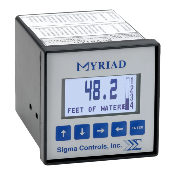
- Page 1 MYRIAD ‘QLC’ 4-CHANNEL MONITOR/CONTROLLER INSTRUCTION MANUAL VISIT OUR WEBSITE SIGMACONTROLS.COM MYR QLC MANUAL 013114...
-
Page 2: Table Of Contents
TABLE OF CONTENTS INTRODUCTION………………………………………… Ordering Information Specifications Features WIRING…………………………………………………… Dwg #: 04-143-2 Analog Input Analog Output Digital Input Digital Output PROGRAMMING AND INITIAL SETUP……………... Input Range Selection Terminal Block Detail Initial Setup & Programming Overview/Key Description TROUBLESHOOTING & MAINTENANCE ………….. 15 APPENDIX ‘A’……………………………………………... -
Page 3: Introduction
INTRODUCTION: The Sigma Myriad QLC (Monitor/Controller) is a 4-channel microprocessor based, state of the art, process/level monitor/controller offering unmatched performance and full user configurability. The QLC is used with primary measuring devices, whose input signal is compatible with common analog outputs 4/20MA, 0-5VDC, 1-5VDC, and 0-10VDC. - Page 4 5 USER KEYS: Up, Down, Left, Right, Enter ACCURACY: 0.1% of calibrated span LOCKOUT: User password, user configurable LINEARIZER 20 point programmable for non linear inputs INPUT IMPEDANCE: Voltage 100K, current 100 OHMS POWER: 120VAC (230VAC available) ENVIRONMENTAL: Operating, 0-65° C Storage, -40°...
-
Page 5: Features
PROGRAMMING: Menu based, all parameters and setpoints are user configurable via menu prompts and user keys. The preconfigured screens and ‘pull down’ sub menus with English prompts assures rapid setup and commissioning. 1 YEAR WARRANTY OPTIONS: Expansion cards, networking M.V. NET: Network allows multiple units to be connected together for distributed applications, remote monitoring SCADA applications. - Page 6 WIRING DETAIL Inputs/Output see Dwg # 04-143-2 All electrical wiring must be in accordance with all local state and national codes that apply. Do not exceed the rated current of the D.C. power supply (100MA) or the form ’C’ relay outputs (5A/240VAC resistive). CAUTION Hazardous voltages are present within the enclosure.
- Page 8 PROGRAMMING & SETUP The Myriad QLC offers multiple ‘Main’ screens allowing the user to view the four input channels in different ways. The options are as follows: Individual Channel Screens: Shows a selected channel in numeric and graphical formats with engineering units and channel number.
- Page 9 In the example shown above, relay 2 and 4 are active, digital output 2 is active and digital input 4 is active. Any active point will be indicated as shown. From any of the status screens press ‘ENTER’ to access the ‘password screen’ and the programming screens.
- Page 10 Note on non linear inputs The Myriad QLC offers a 20 point linearizer which allows the user to customize the indicated display for 20 points of input signal. This feature is often used to read volume in a non-linear vessel such as a horizontal tank with domed end caps.
- Page 11 Input Scaling to Engineering Units: NOTE: This screen sets what the Myriad QLC displays in its ‘default screen’ for the selected input. The example shown above will display 0.0 units when the input is 4.00 MA. Both the input and the...
- Page 12 A) With the cursor selecting ‘INPUT = 4.00’ use the ↑ ↓ buttons to change the input value for the required displayed value. B) Use the → ← buttons to move the cursor to the ‘display’ value and the ↑ ↓ buttons to change the desired display for the previously selected input.
- Page 13 Return to Menu 1 and select ‘DIN’ to program digital inputs. DIN: The Myriad QLC is provided with four digital inputs which when activated will ‘turn on’ their respective relay outputs, i.e. channel 1 digital input ‘on’ will turn on relay output 1.
- Page 14 To reset a channel to the current value, press the ↑ and ← simultaneously to clear channel 1, the ↓ and ← for channel 3, the ↑ and → for channel 2 and the ↓ and → for channel 4. From the Menu 2 window, scroll to ‘SETUP’...
- Page 15 MAINTENANCE AND TROUBLE SHOOTING MAINTENANCE: The Myriad QLC is a digital solid state device which requires no periodic maintenance. Occasional physical checks of the unit should be carried out for physical and mechanical security of mounting, terminal blocks, and electrical wiring.
- Page 16 If D.C. voltage is present, reconnect the negative wire of the supply and insert a milliamp meter between the positive wires. The loop should provide a signal between 4 and 20 MA. If no current is present or the current exceeds 20MA consult the level instrument supplier. If D.C.
- Page 17 APPENDIX ‘A’ SWITCH SELECTION OF ANALOG INPUT RANGES (Factory default 4/20MA). The range dip switches are located on the bottom of the main circuit board. Disconnect power, remove two rear screws, remove terminal strips and slide the entire unit out of its case. Turn the unit upside down to locate the range dip switches.
-
Page 18: Warranty
WARRANTY All Sigma Controls, Inc. products are warranted to be free from defective materials and workmanship for one (1) year from date of shipment. Sigma reserves the right to repair or replace at its option any product found to be defective. In no event shall Sigma Controls, Inc.
Need help?
Do you have a question about the MYRIAD QLC and is the answer not in the manual?
Questions and answers